Three Phase Balanced Circuit:
The analysis of Three Phase Balanced Circuit is presented in this section. It is no way different from the analysis of AC systems in general. The relation between voltages, currents and power in delta-connected and star-connected systems has already been discussed in earlier section.
Balanced Three-Phase System-Delta Load:
Figure 9.31(a) shows a three-phase, three-wire, balanced system supplying power to a Three Phase Balanced Circuit delta load. The phase sequence is RYB. We are required to find out the currents in all branches and lines.
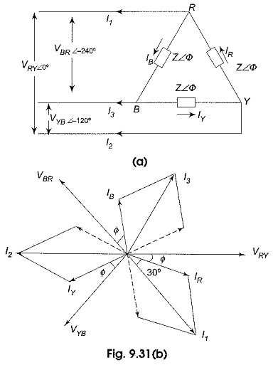
Let us assume the line voltage VRY = V ∠0° as the reference phasor. Then the three source voltages are given by
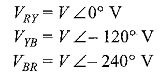
These voltages are represented by phasors in Fig. 9.31(b). Since the load is delta-connected, the line voltage of the source is equal to the phase voltage of the load. The current in phase RY, IR will lag (lead) behind (ahead of) the phase voltage VRY by an angle Φ as dictated by the nature of the load impedance.
The angle of lag of IY with respect to VYB, as well as the angle of lag of IB with respect to VBR will be Φ as the load is balanced. All these quantities are represented in Fig. 9.31(b).
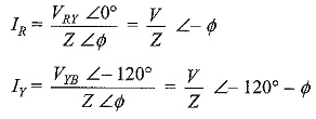
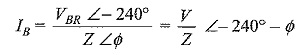
If the load impedance is Z ∠Φ, the current flowing in the three load impedances are then
The line currents are √3 times the phase currents, and are 30° behind their respective phase currents.
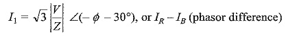
Current in line I is given by
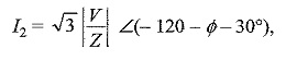
Similarly, the current in line 2
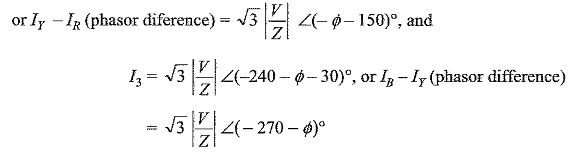
To draw all these quantities vectorially, VRY = V ∠0° is taken as the reference vector.
Balanced Three Phase System-Star Connected Load:
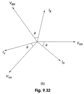
Figure 9.32(a) shows a three-phase, three wire system supplying power to a balanced three phase star connected load. The phase sequence RYB is assumed.
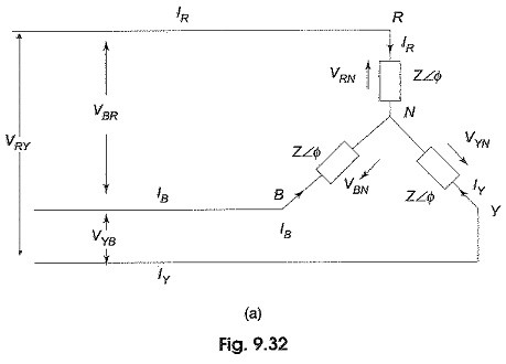
In star connection, whatever current is flowing in the phase is also flowing in the line. The three line (phase) currents are IR, IY and IB.
VRN, VYN and VBN represent three phase voltages of the network, i.e. the voltage between any line and neutral. Let us assume the voltage VRN = V ∠0° as the reference phasor. Consequently, the phase voltage
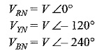
Hence
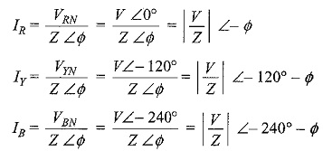
As seen from the above expressions, the currents, IR, IY and IB are equal in magnitude and have a 120° phase difference. The disposition of these vectors is shown in Fig. 9.32(b). Sometimes, a 4th wire, called neutral wire is run from the neutral point, if the source is also star-connected. This gives three-phase, four-wire star-connected system. However, if the three line currents are balanced, the current in the fourth wire is zero, removing this connecting wire between the source neutral and load neutral is, therefore, not going to make any change in the condition of the system. The availability of the neutral wire makes it possible to use all the three phase voltages, as well as the three line voltages. Usually, the neutral is grounded for safety and for the design of insulation.
It makes no difference to the current flowing in the load phases, as well as to the line currents, whether the sources have been connected in star or in delta, provided the voltage across each phase of the delta connected source is √3 times the voltage across each phase of the star-connected source.