Single Phase Half Bridge Inverter | R Load | RL Load | RLC Load:
Figure 11.46(a) gives the circuit configuration of a Single Phase Half Bridge Inverter. It has two thyristors and two free-wheeling diodes. Each thyristor is gated at frequency f = 1/T of the ac supply desired.
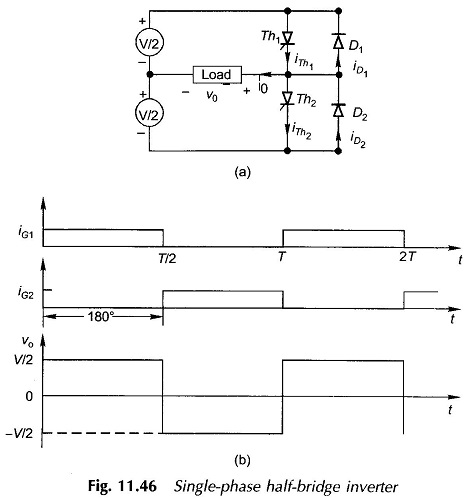
The gating signals of the two thyristors have a phase angle of 180°. From Fig. 11.46(b), the output is easily seen to be rectangular ac waveform of frequency.
![]()
where
- T = triggering period of the thyristor.
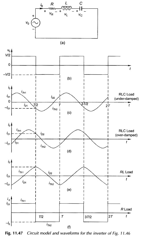
The output waveform feeds the load which may in general comprise RLC components. The Single Phase Half Bridge Inverter circuit model of the inverter is given in Fig. 11.47(a). After several cycles of source voltage νTh have elapsed, the time variation of current settles down to periodic form such that

During the interval 0 < t < T/2,
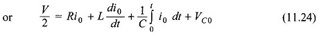
where VC0 is the voltage across the capacitive element at t = 0. Differentiating Eq. (11.24),
![]()
The nature of the waveform will depend upon the circuit damping. The output voltage waveform (rectangular) and various current waveforms for different load characteristics are drawn in Fig. 11.47(b)-(f).
In the Single Phase Half Bridge Inverter with RLC Load underdamped case of Fig. 11.47(c), the current of thyristor Th1 becomes zero and the thyristor turns off before Th2 is gated. The circuit conditions cause the diode D1 to become forward-biased conducting the free-wheeling current iD1. As soon as Th2 is triggered, D1 is reverse-biased and the current is transferred from D1 to Th2. This process then repeats for Th2 and D2 and so on.
In the RLC load overdamped case of Fig. 11.47(d) and the RL load of Fig. 11.47(c), Th1 is forced to switch off (at T/2) while it is still carrying current. As a consequence, the voltage across the L-component of the load reverses, causing D2 to become forward-biased which then conducts the free-wheeling current. As the circuit current tends to reverse, D2 switches off and the current is conducted by Th2 which has already been gated at t = T/2.
For the ideal R load case of Fig. 11.47(f), there is theoretically no free-wheeling current. This does not mean that the free-wheeling diode can be done away with as any practical circuit always has some inductance.