Power Factor by Two Wattmeter Method:
When we talk about the power factor in three-phase circuits, it applies only to balanced circuits, since the power factor in a balanced load is the power factor of any phase. We cannot strictly define the power factor in three-phase unbalanced circuits, as every phase has a separate power factor. The two wattmeter method, when applied to measure power in a three-phase balanced circuits, provides information that help us to calculate the power factor of the load.
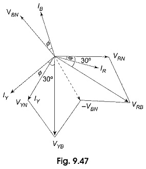
Figure 9.47 shows the vector diagram of the circuit shown in Fig. 9.46. Since the load is assumed to be balanced, we can take Z1 ∠Φ1 = Z2 ∠Φ2 = Z3 ∠Φ3 = Z ∠Φ for the star-connected load. Assuming RYB phase sequence, the three rms load phase voltages are VRN, VYN and VBN. IR, IY and IB are the rms line (phase) currents. These currents will lag behind their respective phase voltages by an angle Φ. (An inductive load is considered).
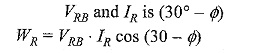
Now consider the readings of the Two Wattmeter Method in Fig. 9.46. WR measures the product of effective value of the current through its current coil IR, effective value of the voltage across its pressure coil VRB and the cosine of the angle between the phasors IR and VRB. The voltage-across the pressure coil of WR is given as follows.
![]()
It is clear from the phasor diagram that the phase angle between
Similarly, WY measures the product of effective value of the current through its current coil IY, the effective value of the voltage across its pressure coil, VYB and the cosine of the angle between the phasors VYB and IY.
![]()
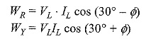
From Fig. 9.47, it is clear that the phase angle between VYB and IY is (30° + Φ).
![]()
Since the load is balanced, the line voltage VRB = VYB = VL and the line current IR = IY = IL
Adding WR and WY gives total power in the circuit, thus
![]()
From the two wattmeter readings, it is clear that for the same load angle Φ, wattmeter WR registers more power when the load is inductive. It is also connected in the leading phase as the phase sequence is RYB. Therefore, WR is higher reading wattmeter in the circuit of Fig. 9.46. In other words, if the load is capacitive, the wattmeter connected in the leading phase reads less for the same load angle. So, if we know the nature of the load, we can easily identify the phase sequence of the system. The higher reading wattmeter always reads positive. By proper manipulation of Two Wattmeter Method readings, we can obtain the power factor of the load.
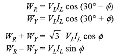
Taking the ratio of the above two values, we get
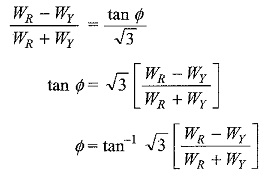
Thereafter, we can find cos Φ