8255 Programming and Operation

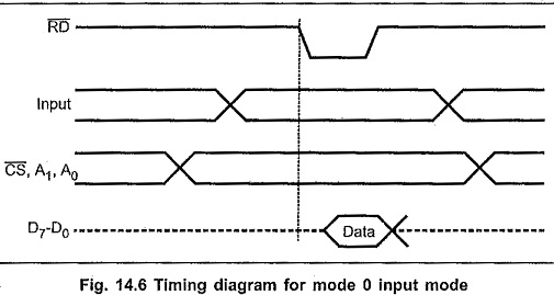
8255 Programming and Operation: The 8255 Programming and Operation are follows Programming in Mode 0: The Ports A, B and C can be configured as simple input or output ports by writing the appropriate control word…

Comments Off on 8255 Programming and Operation

8255 Pin Diagram

8255 Pin Diagram: Fig. 14.1 shows the 8255 Pin Diagram of Microprocessor. 8255 Block Diagram: Fig. 14.2 shows the internal 8255 block diagram of 8255 Pin Diagram Microprocessor. It consists of data bus buffer, control…

Comments Off on 8255 Pin Diagram

8255 Interfacing with 8086

8255 Interfacing with 8086: Fig. 14.17 shows the 8255 Interfacing with 8086 Microprocessor and Interfacing 8255 with 8085 Microprocessor in I/O mapped I/O technique. Here RD and WR signals are activated when IO/M signal is…

Comments Off on 8255 Interfacing with 8086

8253 Programmable Interval Timer

8253 Programmable Interval Timer: 8253 Programmable Interval Timer - In the process control system or automation industry, a number of operations are generally performed sequen­tially. Between two operations, a fixed time delay is specified. In…

Comments Off on 8253 Programmable Interval Timer

8251 Usart

8251 Usart: We know that, 8251A is Universal Synchronous, Asynchronous, Receiver, and Transmitter. Therefore 8251 Usart can take place with four different ways. Asynchronous transmission Asynchronous reception Synchronous transmission Synchronous reception These communication modes can…

Comments Off on 8251 Usart

8251 Pin Diagram

8251 Pin Diagram: Fig. 14.36 shows the 8251 Pin Diagram. Data Bus : Bi-directional, tri-state, 8-bit Data Bus. This pin allow transfer of bytes between the CPU and the 8251A. RD (Read) : A low…

Comments Off on 8251 Pin Diagram

8251 Block Diagram in Microprocessor

8251 Block Diagram in Microprocessor: Fig. 14.37 shows the 8251 Block Diagram in Microprocessor. It includes : Data bus buffer, Read/Write control logic, modem control, Transmit buffer, Transmit Control, Receiver Buffer and Receiver control. Data…

Comments Off on 8251 Block Diagram in Microprocessor

8096 Microprocessor Functional Units

8096 Microprocessor Functional Units: Table 13.2 shows the list of major I/O functions provided by various 8096 Microprocessor Functional Units. Timers: The 8096 Microprocessor Functional Units has two 16 bit timers. The first is designated…

Comments Off on 8096 Microprocessor Functional Units

8096 Microcontroller Architecture Block Diagram

8096 Microcontroller Architecture Block Diagram: Fig. 13.1 shows the internal block diagram of 8096 Microcontroller Architecture Block Diagram. It consists of several functional units, namely CPU with 232 byte register file and register ALU 8-Kbyte…

Comments Off on 8096 Microcontroller Architecture Block Diagram

8096 Memory Space

8096 Memory Space: The addressable memory space on the 8096 Memory Space consists of 64 K bytes, most of which is available to the user for program or data memory. Locations which have special purposes…

Comments Off on 8096 Memory Space