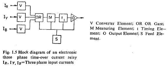
3 Phase Relays:
In a 3 Phase Relays, it is economical to build it on a single phase basis. Thus there will be three converter elements, one for each phase, but thereafter the rest of the 3 Phase Relays circuits (e.g. measuring element, output element, etc.) will be common to all the three circuits. This is shown in Fig. 1.5.
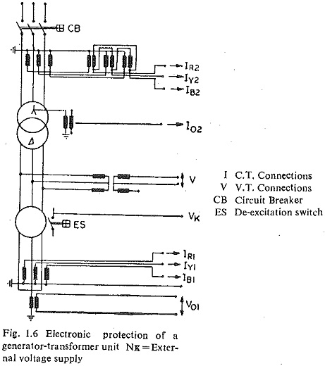
Protective System for Generators and Transformers:
Here again instead of three elements for the individual three phase transformers. These are combined in OR-gates which in turn modulate the high power control units. With this method it is also possible to combine various measuring elements to save unit construction elements. This is shown in Figs. 1.6 and 1.7.
Busbar Protection:
Figs. 1.8 and 1.9 show the static busbar protection scheme. This scheme offers
- high operating speed,
- use of current transformers of any desired characteristic,
- independence of C.T. saturation,
- independence of the effect of load-in resistance,
- application for coupled or subdivided busbars while maintaining the tripping selectivity of each section,
- avoidance of C.T. change over,
- facilities for output signalling, and
- simple extensibility for later extension of the busbar system. In case of
- there is thus no risk of opening of C.T. secondary circuits since change over takes place only in the logic part of the circuit.
In this case of a short circuit fault the protective system will measure each busbar section and operate if all these angles are within ± 90 electrical degrees. The differential current is used as starting quantity, while the reference value is a quantity which is in phase with the short circuit current.