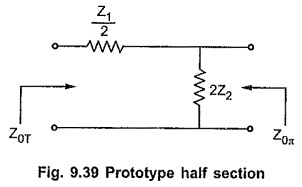
Impedance Matching using Half Sections:
While connecting number of different sections in the filter, it is very important to match the impedances of the sections at the junction points. Thus a T section should not be connected to a π section directly as both the sections have different impedances. Hence it is necessary to use matching sections to join T and π sections together. Such impedance matching section is half section. The half section is derived from either symmetrical T section or symmetrical π section. In symmetrical network, the impedance at both the ports is same. But half section is asymmetrical network and it has two different impedances at the two ports, termed as image impedances. The prototype half section is as shown in the Fig. 9.39.
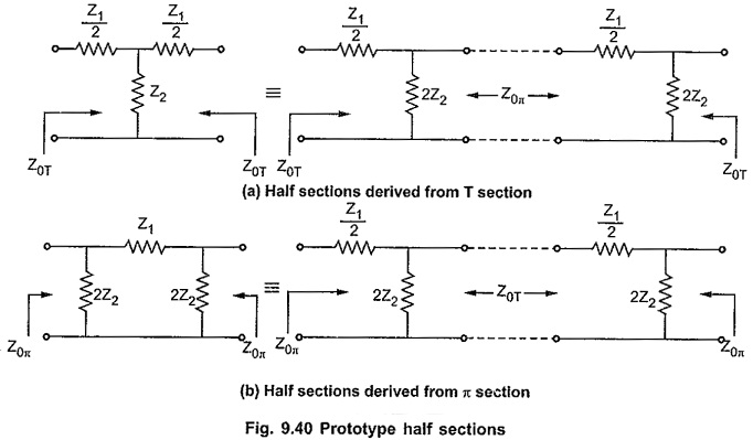
Above prototype half section can be obtained from symmetrical T and π sections by dividing these sections centrally into two half sections as shown in the Fig. 9.40 (a) and (b).
Terminating m-derived Half Sections:
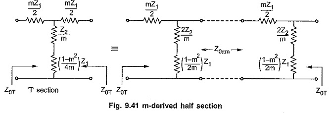
The m-derived half sections can be obtained by splitting m-derived T or π section centrally. When m-derived T section is splitted centrally, the image impedances of the resulting m-derived half sections are Z0T and Z0πm as shown in the Fig. 9.41.
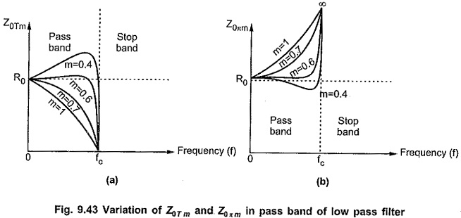
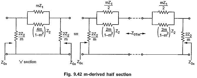
Similarly when m-derived π section is splitted centrally, the image impedances of the resulting m-derived half sections are Z0π and Z0Tm as shown in the Fig. 9.42.
From above half sections, it is clear that the image impedances Z0Tm and Z0πm depend on the value of m. So for different values of m, we can get infinite number of half sections. But it is observed that for m=0.6, the characteristic impedance remains almost constant over entire pass band at value R0. This enables filter to be terminated properly in a pure resistance equal to design impedance R0. The variations of Z0Tm and Z0πm with frequency over a pass band in low pass filter section are as shown in the Fig. 9.43.