Comparison of Different Biasing Circuits:
The Comparison of Different Biasing Circuits of the three basic bias circuits, it must be recalled that transistor manufacturers specify maximum and minimum hFE values for each transistor type number at various levels of collector current. Normally, the current gain of each individual transistor is not known, so that (as already stated) the specified maximum and minimum values of hFE must be used when analyzing (or designing) a transistor bias circuit. It is completely impractical to use some kind of average hFE value.
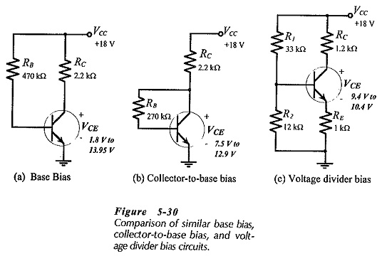
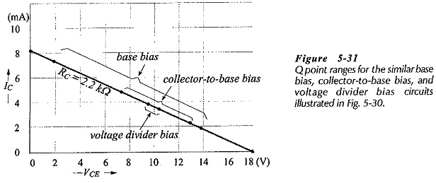
Consider the Comparison of Different Biasing Circuits reproduced in Fig. 5-30. Each circuit uses an 18 V supply and has a 2.2 kΩ (total) load resistance. The circuits were analysed in previous section to determine the IC and VCE levels for hFE(min) = 50 and hFE(max) = 200. The calculated VCE levels are indicated on each circuit and listed in Table 5-1. The Q point ranges are also illustrated in Fig. 5-31.
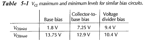
To put these results in the most practical terms, suppose that a base bias circuit is employed as part of a complex electronics system, and that its VCE level is measured as 10 V. lithe transistor fails and has to be replaced with another (same type number) device with an hFE range of 50 to 200, the new VCE level could be anywhere from 1.8 V to 13.95 V. This would normally be unacceptable. A collector-to-base bias circuit in the same circumstance would have a VCE ranging from 7.25 V to 12.9 V when the transistor is replaced. For a voltage divider bias circuit in this situation, the measurable VCE range with a new transistor would be 9.4 V to 10.4 V.
Clearly, collector-to-base bias gives more predictable bias conditions than base bias. Voltage divider bias gives the most predictable bias conditions, because it has the greatest stability against hFE spread
Because of its excellent stability, voltage divider bias is almost always preferable. Collector-to-base bias, or some variation of it, is used in many circuits. Its one major advantage is that the feedback from the collector prevents the transistor from going into saturation. Base bias is most often used in switching circuits.