Skip to content
  • Electrical and Electronics Interview Questions and Answers
    • Electronics Engineering Interview Questions and Answers
    • Electrical Power Engineering Interview Questions and Answers
    • Communication Engineering Interview Questions and Answers
    • Digital Signal Processing Interview Questions and Answers
    • High Voltage Engineering Interview Questions and Answers
    • Total Quality Management Interview Questions and Answers
    • Environmental Engineering Interview Questions and Answers
    • Engineering Physics Interview Questions and Answers
    • Special Electrical Machines Interview Questions and Answers
    • Power System Operation and Control Interview Questions and Answers
    • Protection and Switchgear Interview Questions and Answers
    • Power Electronics Interview Questions and Answers
    • Solid State Drives Interview Questions and Answers
    • Transmission and Distribution Interview Questions and Answers
    • Microprocessor and Microcontroller Interview Questions and Answers
    • READ MORE –>
  • Viva Questions and Answers
    • Electrical Engineering viva Questions and Answers
    • Electronics Communication Engineering viva Questions and Answers
  • Multiple Choice Questions with Answers
    • Electronics Engineering Multiple Choice Questions with Answers
    • Electrical Power Engineering Multiple Choice Questions with Answers
  • Comparisons in Electrical and Electronics
    • Difference between 80186 and 80286 Microprocessor
    • Difference Between Frequency Modulation and Phase Modulation
    • Difference Between Star and Delta Connections
    • Difference Between Electric Circuit and Magnetic Circuit
    • Difference between Combinational Circuit and Sequential Circuit
    • Difference between Static RAM and Dynamic RAM
    • Difference between Linear Power Supply and SMPS
    • Difference Between Thyristor and Transistor
    • Difference Between PAM, PWM and PPM
    • Difference between Voltage Amplifier and Power Amplifier
    • Difference between Zener Breakdown and Avalanche Breakdown
    • Difference between Static Relay and Electromagnetic Relay
    • Difference between Isolator and Circuit Breaker
    • Difference between JFET and MOSFET
    • Difference between NMOS and PMOS
    • READ MORE –>
EEEGUIDE.COM
  • HOME
  • Electronics Engineering
    • Electronic Communication
    • Electronic Instrumentation
    • Electronic Devices and Circuits
    • Microprocessors and Microcontrollers
  • Electrical Power Engineering
    • Electrical Machines
    • High Voltage Engineering
    • Electric Drives
    • Fundamentals of Electrical Drives
  • Circuits and Networks
    • Integrated Circuits
    • Network Analysis and Synthesis
  • Modern Power System
    • Principles of Power System
    • Power System Protection and Switchgear
    • Power Plant Engineering
Menu Close
Search this website
  • Electronics Engineering
  • Electronic Communication
  • Electronic Instrumentation
  • Electronic Devices
  • Microprocessors and Microcontrollers
  • Electrical Power Engineering
  • Electrical Machines
  • Electrical Drives
  • High Voltage Engineering
  • Circuits and Networks
  • Integrated Circuits
  • Network Analysis and Synthesis
  • Modern Power System
  • Principles of Power System
  • Power System Protection and Switchgear
  • Power Plant Engineering
  • Interview Questions and Answers
  • Multiple Choice Questions with Answers
  • Comparisons in Electrical and Electronics
  • Viva Questions and Answers
Electronics Engineering / Non Linear Wave Shaping

Transistor Current Sweep Circuit

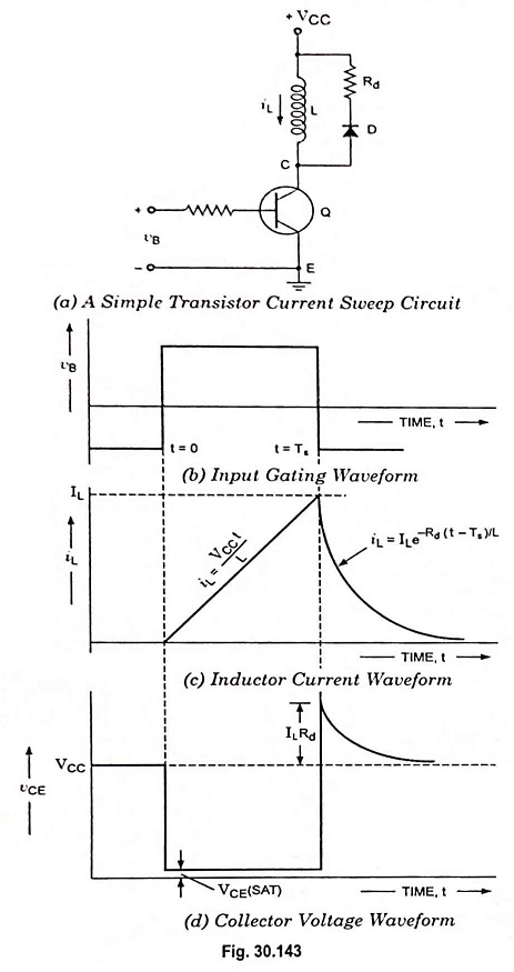
Transistor Current Sweep Circuit: A simple transistor current sweep circuit is given in Fig. 30.143 (a). In the circuit the transistor is employed as an electronic switch and the inductor in series with the transistor…

Comments Off on Transistor Current Sweep Circuit
November 3, 2022
Read more about the article Transistor Current Sweep Circuit
Electronics Engineering / Non Linear Wave Shaping

Miller Sweep Circuit and Miller Bootstrap Sweep Circuit

Miller Sweep Circuit and Miller Bootstrap Sweep Circuit: The basic R-C sweep circuit is shown in Fig. 30.134, in which opening of switch S provides sweep voltage, as already explained earlier. The waveform generated by…

Comments Off on Miller Sweep Circuit and Miller Bootstrap Sweep Circuit
November 3, 2022
Read more about the article Miller Sweep Circuit and Miller Bootstrap Sweep Circuit
Electronics Engineering / Non Linear Wave Shaping

Sawtooth Voltage Generator Circuit Diagram and Waveforms

Sawtooth Voltage Generator Circuit Diagram and Waveforms: Figure 30.129 represents a basic sawtooth voltage generator. Switch S periodically changes its position from point 1 to point 2 (although a mechanical switch is shown in the…

Comments Off on Sawtooth Voltage Generator Circuit Diagram and Waveforms
November 3, 2022
Read more about the article Sawtooth Voltage Generator Circuit Diagram and Waveforms
Electronics Engineering / Non Linear Wave Shaping

Methods of Sweep Voltage Generation

Methods of Sweep Voltage Generation: It is not possible to achieve precise linearity in sweep voltages by electronic means, various methods of sweep voltage generation are enumerated below. 1. Exponential Charging: In this method of…

Comments Off on Methods of Sweep Voltage Generation
November 3, 2022
Electronics Engineering / Non Linear Wave Shaping

Time Base Generator – Working Principle and Types

Time Base Generator - Working Principle and Types: Time base is an axis, normally X-axis, that is used to represent time so that variations of quantities such as voltages, currents etc., or their waveforms can…

Comments Off on Time Base Generator – Working Principle and Types
November 3, 2022
Read more about the article Time Base Generator – Working Principle and Types
Electronics Engineering / Non Linear Wave Shaping

Peak to Peak Detector – Working Principle and Applications

Peak to Peak Detector - Working Principle and Applications: A half-wave rectifier with a capacitor-input filter provides a dc output voltage roughly equal to the peak of the input signal. The same circuit with a…

Comments Off on Peak to Peak Detector – Working Principle and Applications
November 3, 2022
Read more about the article Peak to Peak Detector – Working Principle and Applications
Electronics Engineering / Non Linear Wave Shaping

Clamping Circuit Theorem

Clamping Circuit Theorem: Under steady-state conditions, for any input waveform, the shape of the output waveform of a clamping circuit is fixed and also the area in the forward direction and the area in the…

Comments Off on Clamping Circuit Theorem
November 3, 2022
Read more about the article Clamping Circuit Theorem
Electronics Engineering / Non Linear Wave Shaping

Diode Clamping Circuit – Positive and Negative Clamping

Diode Clamping Circuit - Positive and Negative Clamping: Diode Clamping Circuit - A circuit that places either the +ve or -ve peak of a signal at a desired level is known as a clamping circuit.…

Comments Off on Diode Clamping Circuit – Positive and Negative Clamping
November 2, 2022
Read more about the article Diode Clamping Circuit – Positive and Negative Clamping
Electronics Engineering / Non Linear Wave Shaping

What is Comparator in Electronics? – Classification and Applications

What is Comparator in Electronics? - Classification and Applications A circuit used to mark the instant when an arbitrary waveform attains some particular reference level is called a comparator. The clipping circuits can also be…

Comments Off on What is Comparator in Electronics? – Classification and Applications
November 2, 2022
Read more about the article What is Comparator in Electronics? – Classification and Applications
Electronics Engineering / Non Linear Wave Shaping

Emitter Coupled Clipper Circuit

Emitter Coupled Clipper Circuit: An emitter coupled clipper using two transistors is shown in Fig. 30.71. It is a two level clipper in which the input is applied to the base of one of the…

Comments Off on Emitter Coupled Clipper Circuit
November 2, 2022
Read more about the article Emitter Coupled Clipper Circuit
  • Go to the previous page
  • 1
  • …
  • 22
  • 23
  • 24
  • 25
  • 26
  • 27
  • 28
  • …
  • 43
  • Go to the next page

Main Categories

  • Circuits and Networks
  • Electrical Machines
  • Electrical Power Engineering
  • Electronics Engineering
  • Electronic Communication Systems
  • Electronic Devices and Circuits
  • Electronic Instrumentation
  • High Voltage Engineering
  • Integrated Circuits
  • Electric Drives
  • Fundamentals of Electrical Drives
  • Microprocessors and Microcontrollers
  • Modern Power System
  • Network Analysis and Synthesis
  • Principles of Power System
  • Power System Protection and Switchgear
  • Power Plant Engineering
  • Comparisons in Electrical and Electronics
  • Electrical and Electronics Job Interview Questions and Answers
  • Multiple Choice Questions with Answers (MCQs)
  • Viva Questions and Answers

Recent Posts

  • Step up Chopper – Definition, Circuit Diagram and its Working Principle
  • Transistor approximation (Ideal, Second and Higher)
  • What is Wave Particle Duality?
  • Small Signal Model of FET
  • Pin Photodiode – Definition, Working and Applications
  • What is Excess-3 Code? (Definition and Examples)
  • OTA as Programmable Resistor, Grounded Resistor and Floating Resistor
  • What is Low Frequency Compensation?
  • Basic Elements of Digital Communication System
  • What is Transistor Biasing? – Types of Biasing
  • Blocking Oscillator – Definition, Operation and Types
  • SCR as Half Wave Rectifier Circuit Diagram
  • What is Electron Emission?
  • What is Dual Power Supply? -Circuit Diagram and its Workings
  • Transistor as an Amplifier – Circuit Diagram and Its Workings

Active users on site

  • HOME
  • PRIVACY POLICY
  • CONTACT US
  • SITEMAP
COPYRIGHT © 2014 TO 2025 EEEGUIDE.COM ALL RIGHTS RESERVED