Skip to content
  • Electrical and Electronics Interview Questions and Answers
    • Electronics Engineering Interview Questions and Answers
    • Electrical Power Engineering Interview Questions and Answers
    • Communication Engineering Interview Questions and Answers
    • Digital Signal Processing Interview Questions and Answers
    • High Voltage Engineering Interview Questions and Answers
    • Total Quality Management Interview Questions and Answers
    • Environmental Engineering Interview Questions and Answers
    • Engineering Physics Interview Questions and Answers
    • Special Electrical Machines Interview Questions and Answers
    • Power System Operation and Control Interview Questions and Answers
    • Protection and Switchgear Interview Questions and Answers
    • Power Electronics Interview Questions and Answers
    • Solid State Drives Interview Questions and Answers
    • Transmission and Distribution Interview Questions and Answers
    • Microprocessor and Microcontroller Interview Questions and Answers
    • READ MORE –>
  • Viva Questions and Answers
    • Electrical Engineering viva Questions and Answers
    • Electronics Communication Engineering viva Questions and Answers
  • Multiple Choice Questions with Answers
    • Electronics Engineering Multiple Choice Questions with Answers
    • Electrical Power Engineering Multiple Choice Questions with Answers
  • Comparisons in Electrical and Electronics
    • Difference between 80186 and 80286 Microprocessor
    • Difference Between Frequency Modulation and Phase Modulation
    • Difference Between Star and Delta Connections
    • Difference Between Electric Circuit and Magnetic Circuit
    • Difference between Combinational Circuit and Sequential Circuit
    • Difference between Static RAM and Dynamic RAM
    • Difference between Linear Power Supply and SMPS
    • Difference Between Thyristor and Transistor
    • Difference Between PAM, PWM and PPM
    • Difference between Voltage Amplifier and Power Amplifier
    • Difference between Zener Breakdown and Avalanche Breakdown
    • Difference between Static Relay and Electromagnetic Relay
    • Difference between Isolator and Circuit Breaker
    • Difference between JFET and MOSFET
    • Difference between NMOS and PMOS
    • READ MORE –>
EEEGUIDE.COM
  • HOME
  • Electronics Engineering
    • Electronic Communication
    • Electronic Instrumentation
    • Electronic Devices and Circuits
    • Microprocessors and Microcontrollers
  • Electrical Power Engineering
    • Electrical Machines
    • High Voltage Engineering
    • Electric Drives
    • Fundamentals of Electrical Drives
  • Circuits and Networks
    • Integrated Circuits
    • Network Analysis and Synthesis
  • Modern Power System
    • Principles of Power System
    • Power System Protection and Switchgear
    • Power Plant Engineering
Menu Close
Search this website
  • Electronics Engineering
  • Electronic Communication
  • Electronic Instrumentation
  • Electronic Devices
  • Microprocessors and Microcontrollers
  • Electrical Power Engineering
  • Electrical Machines
  • Electrical Drives
  • High Voltage Engineering
  • Circuits and Networks
  • Integrated Circuits
  • Network Analysis and Synthesis
  • Modern Power System
  • Principles of Power System
  • Power System Protection and Switchgear
  • Power Plant Engineering
  • Interview Questions and Answers
  • Multiple Choice Questions with Answers
  • Comparisons in Electrical and Electronics
  • Viva Questions and Answers
Electronics Engineering / Operational Transconductance Amplifier

What is Current Conveyors (CCs)?

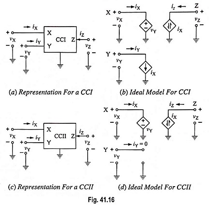
What is Current Conveyors (CCs)? Current conveyors (CCs) were first introduced by Smith and Sedra and have been used in a variety of electronic applications. The CC is a three-port device described by the hybrid…

Comments Off on What is Current Conveyors (CCs)?
November 2, 2022
Read more about the article What is Current Conveyors (CCs)?
Electronics Engineering / Operational Transconductance Amplifier

OTA in Sample and Hold Circuits

OTA in Sample and Hold Circuits: The OTA can be used in sample and hold circuits, as shown in Fig. 41.15. To sample and hold the input signal the control terminal is biased on (=…

Comments Off on OTA in Sample and Hold Circuits
November 2, 2022
Read more about the article OTA in Sample and Hold Circuits
Electronics Engineering / Operational Transconductance Amplifier

OTA Based Ground Inductor and Floating Inductor

OTA Based Ground Inductor and Floating Inductor: The OTA Based ground inductor can be realized by using 2 OTAs as shown in Fig. 41.11. Using Eq. (41.1), we have and Also we have where Vc…

Comments Off on OTA Based Ground Inductor and Floating Inductor
November 2, 2022
Read more about the article OTA Based Ground Inductor and Floating Inductor
Electronics Engineering / Operational Transconductance Amplifier

OTA Adder (Summer) and OTA Lossy Integrator

OTA Adder (Summer) and OTA Lossy Integrator: OTA Adder (Summer) : OTA adder is shown in Fig. 41.9 for which the output voltage is given as where G = 1/R. This circuit is versatile because…

Comments Off on OTA Adder (Summer) and OTA Lossy Integrator
November 2, 2022
Read more about the article OTA Adder (Summer) and OTA Lossy Integrator
Electronics Engineering / Operational Transconductance Amplifier

OTA as Programmable Resistor, Grounded Resistor and Floating Resistor

OTA as Programmable Resistor, Grounded Resistor and Floating Resistor: OTA as a Programmable Resistor: We may employ Ic OTA as a programmable resistor whose resistance is controlled by controlling current Ic. We can define resistance,…

Comments Off on OTA as Programmable Resistor, Grounded Resistor and Floating Resistor
November 2, 2022
Read more about the article OTA as Programmable Resistor, Grounded Resistor and Floating Resistor
Electronics Engineering / Operational Transconductance Amplifier

OTA Voltage Amplifier Circuit Diagram

OTA Voltage Amplifier Circuit Diagram: A basic OTA voltage amplifier circuit diagram is shown in Fig. 41.4. At room temperature (T = 300 K), the output current, Now, if the whole output current Iout flows…

Comments Off on OTA Voltage Amplifier Circuit Diagram
November 2, 2022
Read more about the article OTA Voltage Amplifier Circuit Diagram
Electronics Engineering / Operational Transconductance Amplifier

Operational Transconductance Amplifier (OTA)

Operational Transconductance Amplifier (OTA): The operational amplifiers considered up to this point have been voltage amplifiers. The input signal is a voltage and the output signal is a voltage. Another type of op-amp is an…

Comments Off on Operational Transconductance Amplifier (OTA)
November 2, 2022
Read more about the article Operational Transconductance Amplifier (OTA)

Main Categories

  • Circuits and Networks
  • Electrical Machines
  • Electrical Power Engineering
  • Electronics Engineering
  • Electronic Communication Systems
  • Electronic Devices and Circuits
  • Electronic Instrumentation
  • High Voltage Engineering
  • Integrated Circuits
  • Electric Drives
  • Fundamentals of Electrical Drives
  • Microprocessors and Microcontrollers
  • Modern Power System
  • Network Analysis and Synthesis
  • Principles of Power System
  • Power System Protection and Switchgear
  • Power Plant Engineering
  • Comparisons in Electrical and Electronics
  • Electrical and Electronics Job Interview Questions and Answers
  • Multiple Choice Questions with Answers (MCQs)
  • Viva Questions and Answers

Recent Posts

  • Carrier Concentration in Intrinsic Semiconductor
  • Transistor Construction
  • RC Coupled Transistor Amplifier – Operations, Derivation and Applications
  • Cellular Mobile Radio System – Structure and its Workings
  • n Stage Cascaded Amplifier
  • Ebers Moll Model for PNP Transistor
  • Space Charge Region at a Junction
  • Self Bias or Potential Divider Bias Circuit
  • Complementary Symmetry Push Pull Amplifier
  • FET Biasing Methods – Fixed Bias, Self Bias, Potential Divider Bias and Current Source Bias
  • Thyratron Working Principle
  • Zener Diode Application
  • What is Crossover Distortion and how to eliminate it?
  • Impedance Coupled Transistor Amplifier
  • Transformer Coupled Class A Power Amplifier

Active users on site

  • HOME
  • PRIVACY POLICY
  • CONTACT US
  • SITEMAP
COPYRIGHT © 2014 TO 2025 EEEGUIDE.COM ALL RIGHTS RESERVED