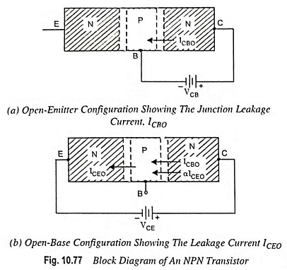
Leakage Current in a Transistor and Breakdown Voltage
Leakage Current in a Transistor and Breakdown Voltage: Leakage Currents: In CB circuits shown in Fig. 10.77, if emitter current is made zero, the B-C junction still remains reverse biased and therefore, a reverse-bias leakage…
Comments Off on Leakage Current in a Transistor and Breakdown Voltage
October 17, 2022