Signal Generator in Electronic Instrumentation

Beat Frequency Oscillator (BFO)

Beat Frequency Oscillator

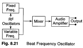
Beat Frequency Oscillator (BFO) | Block Diagram | Working and Limitations: In this Beat Frequency Oscillator, the outputs of two RF oscillators are applied to a square law detector and the resulting difference frequency is amplified. The main advantage of this type of oscillator is that a stable continuous output covering the entire AF range […]

Beat Frequency Oscillator (BFO) Read More »

Circuit Connections for Producing a Vectrogram and Lissajous Pattern

Circuit Connections for Producing a Vectrogram and Lissajous Pattern: This test instrument combines a keyed colour bar generator with an oscilloscope and is used for alignment and testing the colour section of a TV receiver. The amplitude and phase of the chrominance signal represents the colour saturation and hue of the scene. This information can

Circuit Connections for Producing a Vectrogram and Lissajous Pattern Read More »

Color Bar Generator

Color Bar Generator: The composite video signal at the output of a video detector consists of luminance Y signals, the chrominance signal, the color burst, sync pulses and blanking pulses. The amplitude of the video signal varies continuously due to the changing picture content, such a waveform is not useful for adjustment and trouble shooting

Color Bar Generator Read More »

Video Test Pattern Generator

Video Test Pattern Generator: A pattern generator provides video signals directly, and with RF modulation, on standard TV channels for alignment, testing and servicing of TV receivers. The output signal is designed to produce simple geometric patterns like vertical and horizontal bars, checkerboard, cross-hatch, dots, etc. These video test pattern generator are used for linearity

Video Test Pattern Generator Read More »

Marker Generator

Marker Generator Block Diagram: Marker Generator – The sweep generator provides a visual display of the characteristics of the circuit or amplifier, but this is inadequate because it does not give any precise information of the frequency on the traced curve. For this, a separate RF generator, known as the Marker generator is used. This

Marker Generator Read More »

RF Signal Generator

RF Signal Generator

RF Signal Generator: An RF signal generator, when used for alignment and testing of the RF and IF stages of a TV receiver, permits recording of circuit performance at one frequency at a time. Therefore, plotting the total response curve point by point over the entire channel bandwidth becomes a laborious process and takes a

RF Signal Generator Read More »

Block Diagram of Sweep Generator

Sweep Generator

Block Diagram of Sweep Generator: Block Diagram of Sweep Generator – It provides a sinusoidal output voltage whose frequency varies smoothly and continuously over an entire frequency band, usually at an audio rate. The process of frequency modulation may be accomplished electronically or mechanically. It is done electronically by using the modulating voltage to vary

Block Diagram of Sweep Generator Read More »

Function Generator Block Diagram

Function Generator

Function Generator Block Diagram: A Function Generator Block Diagram produces different waveforms of adjustable frequency. The common output waveforms are the sine, square, triangular and sawtooth waves. The frequency may be adjusted, from a fraction of a Hertz to several hundred kHz. The various outputs of the generator can be made available at the same

Function Generator Block Diagram Read More »

Scroll to Top