PLC Hardware Components
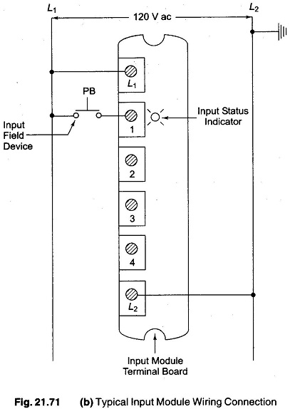
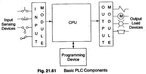
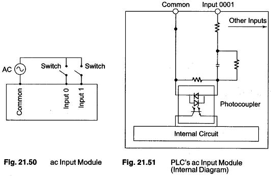
PLC Hardware Components: 1. PLC Hardware Components - The input and output interface modules consists of an I/0 rack and individual I/O modules. Input interface modules, accept signals from the machine or process devices (120V…
Comments Off on PLC Hardware Components
September 29, 2017