Master Control:
Master control can be considered the emergency stop switches. An emergency stop switch typically is a big red button on a machine that will shut it off in cases of emergency. It is commonly abbreviated as MC/MCR (Master control / Master Control Reset), MCS/MCR (Master Control Set/Master Control reset) or just simply MCR (Master control reset)
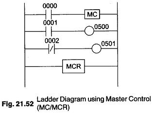
The master control instruction is used in pairs with a master control reset. Some use MCR in pairs instead of putting together with another symbol. Many manufacturers use them differently. Consider the ladder diagram using MCR shown in Fig. 21.52. Let us see how this program will run using different PLCs.
Manufacturer A
In this example, rungs 2 and 3 are only executed when input 0000 is on (true). If input 0000 is not true the PLC pretends that the logic between the MC and MCR instructions does not exist, it would therefore by pass this block of instructions and immediately go to the next rung after the MCR instructions. Conversely, if the input 0000 is true, the PLC would execute rungs 2 and 3 and updates the status of outputs 0500 and 0501 accordingly, so if input 0000 is true, program execution goes to rung 2. If input 0001 is true, 0500 will be true and hence it is on, when the PLC updates the outputs. If input 0002 is true (i.e. physically off) 0501 will be true and therefore it will turn on when the PLC updates the outputs. MCR just tells the PLC “that’s the end of MC/MCR block” .
In this PLC, scan time is not extended when the MC/MCR block is not executed because the PLC pretends the logic in the block does not exist. In other words, the instructions inside the block is not seen by the PLC and therefore it doesn’t execute them.
Manufacture B
In this example, rungs 2 and 3 are always executed immaterial of the status of the input 0000. If the input 0000 is not true,the PLC executes the MC instruction (i.e. MC becomes true) it then forces all the input instruction inside the block to be OFF. If input 0000 is true the MC instruction is made to be false.
Then, if input 0000 is true, program execution goes to rung 2, if input 0001 is true, 0500 will be true and hence it will turn on when the PLC updates the output. If input 0002 is true (i.e. physically off), 0501 will be true and therefore it will turn on when the PLC updates the outputs. MCR just tells the PLC “that’s the end of the MC/MCR block”. When input 0000 is false, inputs 0001 and 0002 are forced off regardless whether they are physically ON or OFF. Therefore outputs 0500 and 0501 will be false.
The difference between manufactuers A and B is that in B scheme the scan time will nearly be the same, whether the block is ON or OFF. This is because the PLC sees each instruction, whether the block is ON or OFF.