Applications of Tropospheric Scatter Links:
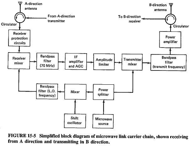
Applications of Tropospheric Scatter Links also known as troposcatter is rather similar to a microwave link terminal, and indeed a typical block diagram is sufficiently like Figure 15-5 that a separate block is not shown.
The main differences lie in the very much higher output powers and lower receiver noise figures in troposcatter links. Typical output powers are 1 to 10 kW, but powers as high as 100 kW have been used for broadband links, although as little as 5 W may be sufficient for a short link designed to carry only eight voice channels. Powers of 1 to 5 kW are achieved with either high-power TWTs or multicavity klystrons, and klystrons are used to provide the higher powers. At 790 to 960 MHz, perhaps the most common frequency range, receivers have low-noise transistor RF amplifiers. In the 2- and 5-GHz ranges, tunnel-diode or parametric amplifiers are common; receiver noise figures under 2 dB are the norm. The attenuation over a troposcatter path is fearful; hence the high transmitting powers used. Everything else being equal, a 3-dB improvement in receiver noise figure may permit a 3-dB reduction in the transmitted power.
Diversity is always used in Applications of Tropospheric Scatter Links. It may be space, polarization, or frequency diversity, or quadruple diversity a combination of any two of those where fading is particularly severe, i.e., on most longer links. This causes added ‘ terminal complexity, but it results in greatly improved reliability. For ‘example, most modem systems are unavailable, because of fading, for an average of less than 0.1 percent of the time during the worst month of the year.
A high proportion of Applications of Tropospheric Scatter Links is single-span, although others may have up to 20 spans. This depends on circumstances. A point-to-point link over inaccessible terrain is likely to be single-span, with a length of 300 to 1000 km. A link designed to provide communications for a group of islands, such as in the Caribbean, Indonesia or the Philippines, will have several spans, with baseband access at each point. Antenna diameters vary correspondingly, with typical diameters of 15 m for broadband links. Longer paths may require parabolic reflectors with diameters as large as 40 m, making them even larger than satellite earth station antennas.
A typical broadband link may carry 192 two-way voice channels, i.e., three supergroups plus one group. Capacities in excess of five supergroups are, however, available, and indeed some shorter links can even carry TV.
Finally, it should be noted that the capital cost of Applications of Tropospheric Scatter Links, in dollars per circuit-kilometer, is perhaps four times that of coaxial cable, making it about 12 times that of microwave links. Operating costs are roughly in the same proportion, being high for troposcatter because of the high powers required. Accordingly, Applications of Tropospheric Scatter Links are used where special considerations so dictate, rather than interchangeably with the other two broadband transmission media.
Fiber Optic Links:
It was shown already how coherent waves at light and infrared frequencies may be generated (with lasers or light-emitting diodes) and how they may be detected (with photodiodes). It now remains to discuss the intervening medium, which unfortunately cannot be open space at least not on the earth’s surface. This is because light or infrared is subject to far too much absorption in open space, be it by the moisture content and dust in the air or, worse still, fog or rain. Similarly, plenty of interference can be expected from the many light sources in constant use. Accordingly, optical fibers are used for light and infrared transmissions, in a manner virtually identical to waveguides at microwave frequencies. Because of the importance of this form of communications system and its relevance to today’s communication industry