Delay Line in Triggered Sweep Circuit:
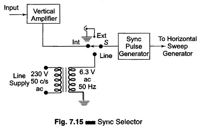
Figure 7.13 shows a Delay Line in Triggered Sweep Circuit. Figure 7.14 indicates the amplitude of the signal wrt time and the relative position of the sweep generator output signal.
The diagram shows that when the delay line is not used, the initial part of the signal is lost and only part of the signal is displayed. To counteract this disadvantage the signal is not applied directly to the vertical plates but is passed through a delay line circuit, as shown in Fig. 7.13. This gives time for the sweep to start at the horizontal plates before the signal has reached the vertical plates.
The trigger pulse is Picked off at a tune to after the signal has passed through the main amplifier. The sweep generator delivers the sweep to the horizontal amplifier and the sweep starts at the HDP at time to + 80 ns. Hence the sweep starts well in time, since the signal arrives at the VDP at time to + 200 ns.
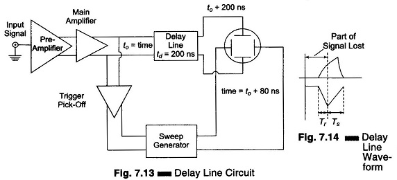
Sync Selector for Continuous Sweep CRO:
The sync selector is a 3-position switch, Int-Ext-Line. Therefore horizontal sweep can be synchronized with the signals coming from any of the three sources, as shown in Fig. 7.15.