Function Generation and Linearisation:
An important aspect of the closed loop control system is the use of Function Generation and Linearisation, e.g. in the control of induction motors there exists a definite nonlinear relationship between the stator current and slip frequency to maintain a constant air gap flux. The function generation can be easily carried out using a microprocessor. This task is very difficult to implement using discrete analog components. Multidimensional functions can also be generated on the microprocessor. This function generation can be accomplished by means of a look-up table in the computer memory. If the microprocessor is sufficiently fast the function generation can be implemented using linear segment computations or curve fitting techniques. The necessity for function generation arises also in the dc motor control and synchronous motor control. In the former it may be required to represent the non-linear magnetisation curve and in the latter to represent the relation between the link current and margin angle in the constant margin angle control.
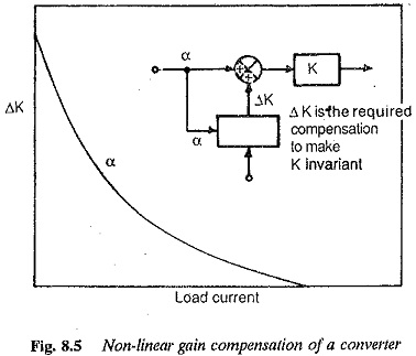
The Function Generation and Linearisation techniques can be very well employed when a microprocessor is used in the control. The non-linear transfer characteristics of the system can be linearised using standard techniques of producing an inverse non-linear function in the processor. The gain of the system varies in the control of a dc motor in the field weakening mode as well as when the converter is in the discontinuous mode of operation. The reduction in the gain causes sluggish operation. The gain compensation in terms of firing angle as a function of Id is a non-linear function. This is shown in Fig. 8.5. This may be linearised by the microprocessor. The inverse non-linear function for Function Generation and Linearisation may be developed using function generation techniques discussed above, e.g., using a look-up table. The necessary corrections may be made to maintain the gain at a constant value.
During discontinuous conduction the converter voltage does not follow the cosine function. At a given firing angle the converter voltage is more if the conduction is discontinuous. A necessary correction to the firing angle is made to bring the voltage to a value corresponding to continuous conduction. A detailed discussion is given in the dc motor control.
Processing the Feedback Signals
Some feedback signals can be determined by sensing. These are the signals of voltage, current and speed. These are analog signals when measured, and have to be converted to digital quantities by suitable A/D converters. The speed, however, can be measured digitally using a shaft encoder and A/D conversion can be avoided. These signals must be processed by the microprocessor for use in feedback loops. Further, the microprocessor should be capable of synthesising the feedback signals, such as torque, flux, etc., which cannot be easily measured. The microprocessor should perform the necessary arithmetic, including multiplication and division, while performing the function of estimating the feedback signals.
Implementation of PWM Techniques
The principles of PWM are employed in the control of inverter for the necessary voltage control in the inverter. These techniques are also used in the control of harmonics in the output voltage. The microprocessor can develop the PWM waveform using all the principles of PWM. These are sinusoidal modulation, or trapezoidal modulation. The necessary reference and carrier waves may be generated in the microprocessor by software programs to determine the points of triggering the thyristors. The technique of look-up table to generate the PWM waveform is very much suited for selective harmonic elimination. The computations to determine the firing instants in any of above methods become time critical at higher frequencies. Therefore at higher frequencies, a look-up table is desirable. The major application of microprocessor finds in the control of ac motors using PWM inverters.
Programmable Time Delay
One of the functions of a microprocessor in the control of variable speed drives is to provide an adjustable delay, e.g., delay angle in the gating of thyristors. This can be accomplished in a microprocessor by means of up or down counters. These are used to increment or decrement a digital word stored in the memory (periodically) until the memory location reaches the final count (in the former) or clears (in the latter). A pulse or an interrupt may be generated at the end of counting to execute the necessary event.
Digital filters can be implemented using a microprocessor. These correspond to analog transfer function and improve the performance of the Function Generation and Linearisation. The compensators explained before are simple digital filters. The microprocessors monitor various signals of the system and also give warning signals in case the variables exceed safe values. They finally issue a signal to shut down the system in case there is no response from the operator. The microprocessor may be programmed to provide the necessary protections against faults. Overcurrent protection, protection against single phasing, etc., may be provided with suitable software in the microprocessor.
A microprocessor performs the functions of data acquisition, sequencing of control for smooth transition from one mode, of operation to the other, tests and diagnostics. It can be programmed to conduct evaluation tests on drive system and no load tests on the motors to determine the parameters. It may be supported by a powerful software to identify the faults. This software may be used if the system is down with a complex fault.