Resonance Bridge for Measurement of Inductance or Capacitance
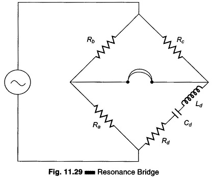
Resonance Bridge for Measurement of Inductance or Capacitance: One arm of this Resonance Bridge, shown in Fig. 11.29, consists of a series resonance circuit. The series resonance circuit is formed by Rd, Cd and Ld…
Comments Off on Resonance Bridge for Measurement of Inductance or Capacitance
March 26, 2022