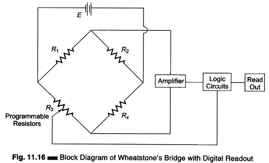
Bridges

Bridge Controlled Error Detection

Bridge Controlled Error Detection

Bridge Controlled Error Detection: Bridge Controlled Error Detection – Whenever a bridge is unbalanced, a potential difference exists at its output terminal. The potential difference causes current to flow through the detector (say, a galvanometer) when the bridge is used as part of a measuring instrument. When the bridge is used as an error detector

Bridge Controlled Error Detection Read More »

Wheatstone Bridge Diagram

Wheatstone Bridge Diagram: A Wheatstone Bridge diagram in its simplest form consists of a network of four resistance arms forming a closed circuit, with a dc source of current applied to two opposite junctions and a current detector connected to the other two junctions, as shown in Fig. 11.1. Wheatstone Bridge diagram are extensively used

Wheatstone Bridge Diagram Read More »

Scroll to Top