Bus Bar Arrangement in Power Station:
When a number of generators or feeders operating at the same voltage have to be directly connected electrically, bus-bars are used as the common electrical component. Bus-bars are copper rods or thin walled tubes and operate at constant voltage. We shall discuss some important Bus Bar Arrangement in Power Station and sub-stations. All the diagrams refer to 3-phase arrangement but are shown in single-phase for simplicity.
1. Single Bus-bar System: The single bus-bar system has the simplest design and is used for power stations. It is also used in small outdoor stations having relatively few outgoing or incoming feeders and lines. Fig. 16.2 shows the single bus-bar system for a typical power station. The generators, outgoing lines and transformers are connected to the bus-bar. Each generator and feeder is controlled by a circuit breaker. The isolators permit to isolate generators, feeders and circuit breakers from the Bus Bar Arrangement in Power Station for maintenance. The chief advantages of this type of arrangement are low initial cost, less maintenance and simple operation.
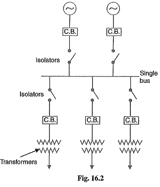
Disadvantages: Single bus-bar system has the following three principal disadvantages :
- The bus-bar cannot be cleaned, repaired or tested without de-energising the whole system.
- If a fault occurs on the bus-bar itself, there is complete interruption of supply.
- Any fault on the system is fed by all the generating capacity, resulting in very large fault
2.Single bus-bar system with Sectionalisation: In large generating stations where several units are installed, it is a common practice to sectionalise the bus so that fault on any section of the bus-bar will not cause complete shut down. This is illustrated in Fig. 16.3 which shows the bus-bar divided into two sections connected by a circuit breaker and isolators. Three principal advantages are claimed for this arrangement. Firstly, if a fault occurs on any section of the bus-bar, that section can be isolated without affecting the supply to other sections. Secondly, if a fault occurs on any feeder, the fault current is much lower than with unsectionalised Bus Bar Arrangement in Power Station. This permits the use of circuit breakers of lower capacity in the feeders. Thirdly, repairs and maintenance of any section of the bus-bar can be carried out by de-energising that section only, eliminating the possibility of complete shut-down.
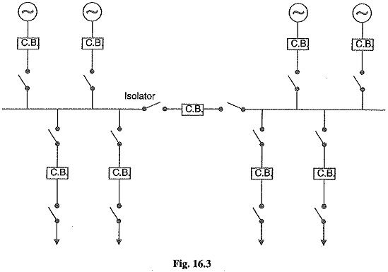
It is worthwhile to keep in mind that a circuit breaker should be used as the sectionalising switch so that uncoupling of the bus-bars may be carried out safely during load transfer. Moreover, the circuit breaker itself should be provided with isolators on both sides so that its maintenance can be done while the bus-bars are alive.
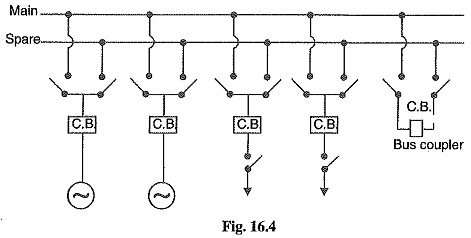
3.Duplicate bus-bar system: In large stations, it is important that breakdowns and maintenance should interfere as little as possible with continuity of supply. In order to achieve this objective, duplicate Bus Bar Arrangement in Power Station is used in important stations. Such a system consists of two bus-bars, a “main bus-bar” and a “spare” bus-bar (see Fig. 16.4). Each generator and feeder may be connected to either bus-bar with the help of bus coupler which consists of a circuit breaker and isolators.
In the scheme shown Main in Fig. 16.4, service is interrupted during switch over from one bus to another. However, if it were desired to switch a circuit from one to another without interruption of service, there would have to be two circuit breakers per circuit. Such an arrangement will be too expensive.
Advantages
- If repair and maintenance it to be carried on the main bus, the supply need not be interrupted as the entire load can be transferred to the spare bus.
- The testing of feeder circuit breakers can be done by putting them on spare bus-bar, thus keeping the main bus-bar undisturbed.
- If a fault occurs on the bus-bar, the continuity of supply to the circuit can be maintained by transferring it to the other Bus Bar Arrangement in Power Station.
Switchgear Accommodation:
The main components of a switchgear are circuit breakers, switches, bus-bars, instruments and instrument transformers. It is necessary to house the switchgear in power stations and sub-stations in such a way so as to safeguard personnel during operation and maintenance and to ensure that the effects of fault on any section of the gear are confined to a limited region. Depending upon the voltage to be handled, switchgear may be broadly classified into
(i) outdoor type
(ii) indoor type.
(i) Outdoor type: For voltages beyond 66 kV, switchgear equipment is installed outdoor. It is because for such voltages, the clearances between conductors and the space required for switches, circuit breakers, transformers and others equipment become so great that it is not economical to install all such equipment indoor.
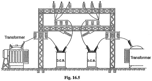
Fig. 16.5 shows a typical outdoor sub-station with switchgear equipment. The circuit breakers, isolators, transformers and bus-bars occupy considerable space on account of large electrical clearance associated with high voltages.
(ii) Indoor type: For voltages below 66 kV, switchgear is generally installed indoor because of economic considerations. The indoor switchgear is generally of metal-clad type. In this type of construction, all live parts are completely enclosed in an earthed metal casing. The primary object of this practice is the definite localisation and restriction of any fault to its place of origin.