BJT Bias Circuit Troubleshooting:
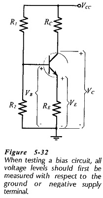
Voltage Measurement – When a BJT Bias Circuit Troubleshooting is constructed in a laboratory situation, the supply voltage (VCC) and the voltage levels at the transistor terminals (VC, VB and VE) should be measured with to the ground or negative supply terminal, as illustrated in Fig. 5-32. When the measured voltages are not as expected, the circuit must be further investigated to locate the fault.
Common Errors:
The following is a list of errors that commonly occur with both experienced and inexperienced individuals:
- Power supply not switched on.
- Power supply current limiter control incorrectly set.
- Cables incorrectly connected to the power supply.
- Volt-Ohm-Milliammeter (VOM) function incorrectly selected.
- Wrong VOM terminals used.
- Incorrect component connections.
- Incorrect resistor values.
- Resistors in the wrong places.
Obviously, it is important to correctly connect the cables to the power supply, and to switch the power supply on. However, with many things to think about, people often neglect basic items. Similarly, it is just too easy to connect the VOM cables to the wrong terminals, or to select the wrong function. With plug-in-type breadboards, the sockets are so small and close together that incorrect connections often occur. These items should all be checked before looking for other circuit faults. Care should also be taken when selecting resistors. For example, a 100 kΩ resistor used instead of a 100 kΩ resistor can have serious consequences.
Base Bias:
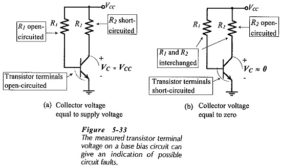
Figure 5-33 illustrates typical error sources in a base biased circuit. Normal voltage levels in a base bias circuit are VBE ≈ 0.7 V, and VC anywhere in the range of 2 V to (VCC – 2 V). If VC = VCC, as in Fig. 5- 33(a), R1 or one of its connecting leads might be open-circuited, or the transistor may have an open-circuited junction. Alternatively, R2 might be shorted. When VC ≈ 0, as in Fig. 5-33(b), R1 and R2 could be in the wrong places; that is, the high-value and low-value resistors might be interchanged. Other possibilities are that R2 is open-circuited, or the transistor CE terminals are short-circuited.
Collector-to-Base Bias:
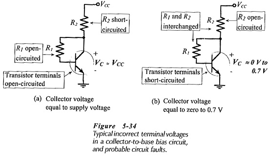
Some reasons for incorrect voltage levels in a collector-to-base bias circuit are illustrated in Fig. 5-34. These are similar to those discussed for the base bias circuit. When VC equals VCC, either resistor R1 or one of the transistor terminals is likely to be open-circuited, [Fig 5-34(a)). If VC is in the range of 0 V to 0.7 V, R1 and R2 might be interchanged, the device terminals might be short-circuited, or R2 might be open-circuited, [Fig 5-34(b)].
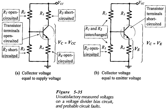
Voltage Divider Bias:
Figure 5-35 shows unsuitable measured voltages and probable errors in a voltage divider of BJT Bias Circuit Troubleshooting. If VC equals VCC, either R1 or R4 might be open-circuited. Alternatively, R2 or R3 might be short-circuited, [Fig. 5-35(a)), or the transistor terminals might be open-circuited. When VC approximately equals VE, R2 might be open-circuited, or R1 and R2 might be interchanged, [Fig. 5-35(b)]. Alternatively, the transistor terminals might be short-circuited.