Unbalanced Three Phase Circuit Analysis:
Types of Unbalanced Loads – An unbalance exists in a circuit when the impedances in one or more phases differ from the impedances of the other phases. In such a case, line or phase currents are different and are displaced from one another by unequal angles. So far, we have considered balanced loads connected to balanced systems. It is enough to solve problems, considering one phase only on balanced loads; the conditions on other two phases being similar. Problems on Unbalanced Three Phase Circuit Analysis are difficult to handle because conditions in the three phases are different. However, the source voltages are assumed to be balanced. If the system is a three-wire system, the currents flowing towards the load in the three lines must add to zero at any given instant. If the system is a four-wire system, the sum of the three outgoing line currents is equal to the return current in the neutral wire. We will now consider different methods to handle unbalanced star-connected and delta-connected loads. In practice, we may come across the following unbalanced loads:
- Unbalanced delta-connected load
- Unbalanced three-wire star-connected load, and
- Unbalanced four-wire star-connected load.
(a)Unbalanced delta-connected load:
Figure 9.33 shows an unbalanced delta-load connected to a balanced three-phase supply.
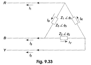
The unbalanced delta-connected load supplied from a balanced three-phase supply does not present any new problems because the voltage across the load phase is fixed. It is independent of the nature of the load and is equal to the line voltage of the supply. The current in each load phase is equal to the line voltage divided by the impedance of that phase. The line current will be the phasor difference of the corresponding phase currents, taking VRY as the reference phasor.
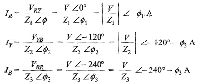
Assuming RYB phase sequence, we have
![]()
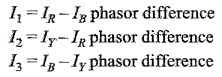
Phase currents are
The three line currents are
(b) Unbalanced Four Wire Star-Connected Load:
Figure 9.35 shows an unbalanced star load connected to a balanced 3-phase, 4-wire supply.
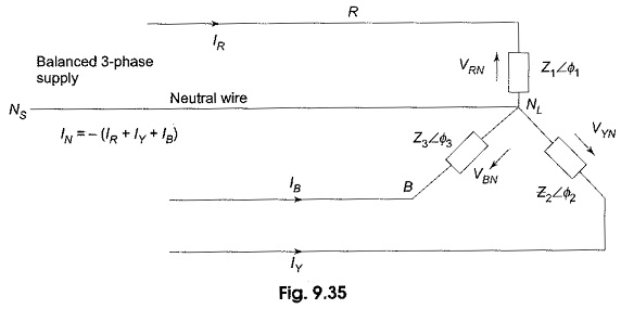
The star point, NL, of the load is connected to the star point, NS of the supply. It is the simplest case of an Unbalanced Three Phase Circuit Analysis because of the presence of the neutral wire; the star points of the supply NS (generator) and the load NL are at the same potential. It means that the voltage across each load impedance is equal to the phase voltage of the supply (generator), i.e. the voltages across the three load impedances are equalized even though load impedances are unequal. However, the current in each phase (or line) will be different. Obviously, the vector sum of the currents in the three lines is not zero, but is equal to neutral current. Phase currents can be calculated in similar way as that followed in an unbalanced, delta-connected load.
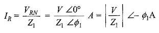
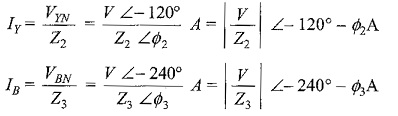
Taking the phase voltage VRN = V∠0° V as reference, and assuming RYB phase sequences, we have the three phase voltages as follows
![]()
The phase currents are
Incidentally, IR, IY and IB are also the line currents; the current in the neutral wire is the vector sum of the three line currents.
(c) Unbalanced Three Wire Star-Connected Load:
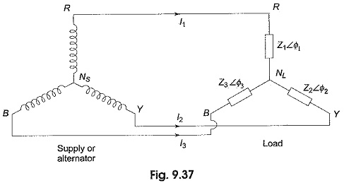
In a three-phase, four-wire system if the connection between supply neutral and load neutral is broken, it would result in an unbalanced three-wire star-load. This type of load is rarely found in practice, because all the three wire star loads are balanced. Such as system is shown in Fig. 9.37. Note that the supply star point (NS) is isolated from the load star point (NL).
The potential of the load star point is different from that of the supply star point. The result is that the load phase voltages is not equal to the supply phase voltage; and they are not only unequal in magnitude, but also subtend angles other than 120° with one another. The magnitude of each phase voltage depends upon the individual phase loads. The potential of the load neutral point changes according to changes in the impedances of the phases, that is why sometimes the load neutral is also called a floating neutral point. All star-connected, unbalanced loads supplied from polyphase systems without a neutral wire have floating neutral point. The phasor sum of the three unbalanced line currents is zero. The phase voltage of the load is not 1/√3 of the line voltage. The unbalanced three-wire star load is difficult to deal with. It is because load phase voltages cannot be determined directly from the given supply line voltages. There are many methods to solve such unbalanced Y-connected loads. Two frequently used methods are presented here. They are
- Star-delta conversion method, and
- The application of Millman’s theorem
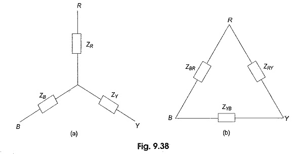
Star-Delta Method to Solve Unbalanced Load:
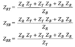
Figure 9.38(a) shows an unbalanced wye-connected load. It has already been shown in Section 9.6 that a three phase star-connected load can be replaced by an equivalent delta-connected load. Thus, the star load of Fig. 9.38(a) can be replaced by equivalent delta as shown in Fig. 9.38(b), where the impedances in each phase is given by
The problem is then solved as an unbalanced delta-connected system. The line currents so calculated are equal in magnitude and phase to those taken by the original unbalanced wye (Y) connected load.
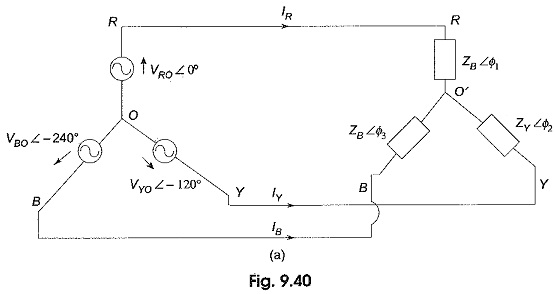
Millman’s Method of Solving Unbalanced Load:
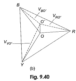
One method of solving an unbalanced three-wire star-connected load by star-delta conversion is described in Section 9.10.5. But this method is laborious and involves lengthy calculations. By using Millman’s theorem, we can solve this type of problems in a much easier way. Consider an unbalanced wye (Y) load connected to a balanced three-phase supply as shown in Fig. 9.40(a). VRO, VYO and VBO are the phase voltages of the supply. They are equal in magnitude, but displaced by 120° from one another. VRO′, VYO′ and VBO′ are the load phase voltages; they are unequal in magnitude as well as differ in phase by unequal angles. ZR, ZY and ZB are the impedances of the branches of the unbalanced wye (Y) connected load. Figure 9.40(b) shows the triangular phasor diagram of the complete system. Distances RY, YB and BR represent the line voltages of the supply as well as load. They are equal in magnitude, but displaced by 120°. Here O is the star-point of the supply and is located at the centre of the equilateral triangle RYB. O’ is the load star point. The star point of the supply which is at the zero potential is different from that of the star point at the load, due to the load being unbalanced. O’ has some potential with respect to O and is shifted away from the centre of the triangle. Distance O’O represents the voltage of the load star point with respect to the star point of the supply Vo′o.
Vo′o is calculated using Millman’s theorem. If Vo′o is known, the load phase voltages and corresponding currents in the unbalanced wye load can be easily determined.
According to Millman’s theorem, Vo′o is given by
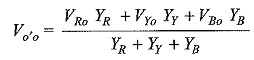
where the parameters YR, Yy and YB are the admittances of the branches of the unbalanced wye connected load. From Fig. 9.40(a), we can write the equation
![]()
or the load phase voltage
![]()
Similarly, VYo′ = VYo – Vo′o and VBo′ = VBo – Vo′o can be calculated. The line currents in the load are
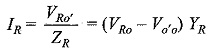
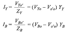
The Unbalanced Three Phase Circuit Analysis can also be determined by using Kirchhoff s laws, and Maxwells mesh or loop equation. In general, any method which gives quick results in a particular case should be used.