Static Scherbius Drive Circuit Diagram:
A basic scheme of a Static Scherbius Drive Circuit Diagram converter cascade, that is employed for recovery of slip power in electrical form itself, is given in Fig. 11.42.
For achieving both subsynchronous and supersynchronous speed control, converters C1 and C2 must be fully-controlled thyristor bridges, one functioning at slip frequency as a rectifier or inverter while the other operates at supply-system frequency as an inverter or rectifier.
The converter cost is quite appreciable and a slip-frequency gating circuit is also required. Moreover, at speeds near synchronous, when the slip-frequency emfs are not adequate for natural commutation, special connections or forced commutation methods are necessary. If converter C1 were an uncontrolled one (diode bridge) the converter cascade and the control unit would become economical and simple, but only subsynchronous speed control would then be possible.
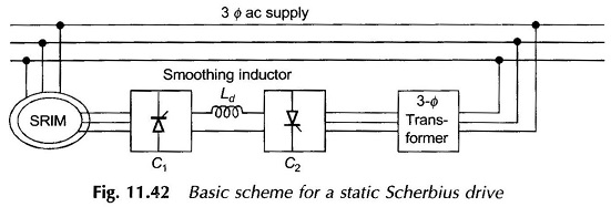
The three-phase transformer between the inverter C2 and the supply network is required with large supply voltages, since the voltage across the sliprings is limited and may be extremely low for direct inversion into the a.c. supply.
Advantages of Static Scherbius Drive:
The principal disadvantage of the sub synchronous cascade drive is its low power factor particularly at reduced speeds. The reactive power consumption of the inverter is largely responsible for the low power factor of the cascade drive.
Applications of Static Scherbius Drive:
The Static Scherbius Drive has applications in large power fan and pump drives which require speed control in a narrow range only. If maximum slip is denoted by Smax, then power ratings of diode bridge, inverter and transformer can be just Smax times the motor power rating resulting in a low cost drive.
This Static Scherbius Drive Circuit Diagram provides a constant torque control. Constant power control is obtained by static Kramer drive.