Static Relays Basics and Classification:
A Static Relays Basics refers to a relay in which the measurement or comparison of electrical quantities is done in a static network which is designed to give an output signal in the tripping direction when a threshold condition is passed. The output signal operates a tripping device which may be electronic, semiconductor or electromagnetic.
Basis for Static Relay Development:
As a result of the great expansion of electrical transmission and distribution systems during the last thirty years and with the advent of much larger power stations and more highly interconnected systems, the duty imposed upon protective gear has become more and more severe. Since relays now have to perform much more complicated functions many types tend to become very complex mechanically and hence costly and difficult to test and to maintain.
The basis of the so-called static relaying is the use of circuits and components to achieve a variety of functions and operating characteristics which for protection purposes have traditionally been obtained using electromechanical devices. Reliability, always important has been emphasized as short-circuit levels, circuit ratings and complexity of interconnection have increased.
Shorter operating times have become more essential to preserve dynamic stability as the character and loading of systems approach design limits. The satisfaction of these requirements has left little potential for further improvements in conventional electromechanical relays.
Until fifteen years ago, relay design was dominated by the use of electromechanical elements. Such an element of whatever basic characteristics, e.g. square law induction element has a dynamic behavior special to that element and design freedom is consequently restricted by factors such as the conflicting requirements of sensitivity and mechanical robustness.
Experience shows that these more exacting requirements can readily be met using new static relays.
Classification of Static Relays:
Static Relays Basics are classified according to the type of the measuring unit or the comparator as follows:
- Electronic relays
- Transductor or magnetic amplifier relays
- Rectifier bridge relays
- Transistor relays
- Hall effect relays and
- Gauss effect relays
1. Electronic relays
These were the first to be developed in the series of static relays. Fitzgerald presented a carrier current pilot relaying scheme for the protection of transmission lines in 1928. Subsequently a series of electronic circuits for most of the common types of protective gear relays were developed. The components used were electronic valves for measuring unit.
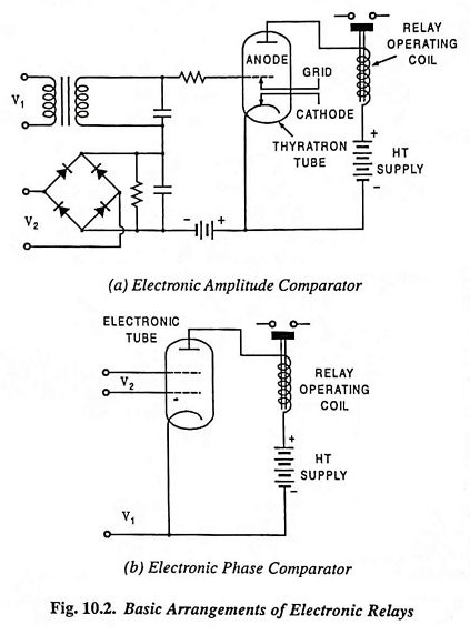
Two basic arrangements are shown in Fig. 10.2. One uses an amplitude comparator [Fig. 10.2 (a)] and the other makes use of a phase comparator [Fig. 10.2 (b)]. In the former arrangement two ac quantities under comparison are rectified and applied in opposition in the control grid circuit of an electronic tube and the operation occurs when one quantity exceeds the other by an amount depending on the bias. In the latter arrangement one ac quantity is connected to the control grid and the other to the screen grid of the electronic tube. Operation occurs when the two ac quantities under comparison are in phase.
Inspite of the advantages of fast operation, low maintenance, low burden on CTs and PTs, absence of mechanical inertia and bouncing contacts, they suffered inherently from the requirements of ht supply, short life, large power consumption, It supply for the heater elements. These relays could not meet practical requirements and hence never reached the commercial stages.
2. Transductor (Magnetic Amplifier Relays)
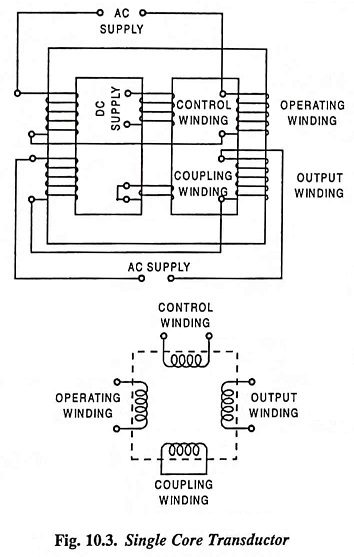
A transductor comprises essentially a magnetic core carrying two groups of windings usually known as operating windings and control windings. Each group may comprise only one winding but if there is more than one winding in a group all those windings are magnetically linked. On the other hand the windings of the different groups are not magnetically linked. The control windings are energized with dc and the operating windings with ac. A transductor operates so as to present a variable impedance to currents flowing through the operating windings the magnitude of this impedance being varied by the current flowing through the control winding. A single core transductor is illustrated in Fig. 10.3.
If transductor is employed as an amplitude comparator its sensitivity is limited due to the sensitivity of the slave relay in its output circuit. On the other hand if it is used as a phase comparator to achieve higher sensitivity it will depend on an external ac supply which is sometimes difficult to arrange.
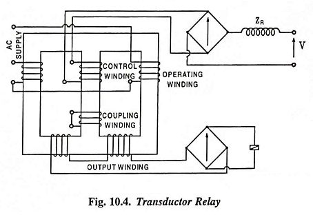
A transductor relay is shown in Fig. 10.4. The restraining voltage is applied to the control winding through an impedance ZR and a rectifier. The restraining current so obtained is rectified and partially smoothed by the short-circuit effect of the rectifier on the control winding and also due to the short-circuited coupling winding. The effect of this is to drive both the limbs on which the operating winding is wound into saturation. The operating winding is wound in such a way that the ampere-turns so produced opposes the restraining ampere-turns in one limb and strengthen them in the other. Assuming equality of restraining and operating turns, and neglecting the finiteness of permeability, the operating current would drive out of saturation, the limb in which operating current opposes the restraining ampere-turns, when the peak value of the operating current exceeds the magnitude of restraining current. When this happens a voltage is induced in the output winding and the relay gets energized. The same operation is repeated on the other limb during next half cycle. The slave relay current is very low until the above mentioned condition exists. Then it suddenly increases and becomes very large for a small value of operating current. That is why a heavy duty telephone type relay is employed with large setting.
The transductor relays are mechanically very simple and are quite reliable. Due to smoothing and rectifying a signal, a delay is introduced because of the time constant of the smoothing circuit and hence the relays are slow in operation and, therefore, are discarded for protection applications.
3. Rectifier Bridge Relays
Such relays became popular because of development of semiconductor diodes. This relay consists of two rectifier bridges and a moving coil or polarized moving iron relay. The most common are relay comparators based on rectifier bridges, which can be arranged as either amplitude or phase comparators.
4. Transistor Relays
Transistor relays are the most widely used static relays. In fact when we talk of static relays we generally mean transistor relays. Transistor which acts like a triode can overcome most of the limitations posed by the electronic valves and thus has made possible to develop the electronic relays more commonly known as static relays. The fact that a transistor can be employed both as an amplifying device and a switching device, makes it suitable for achieving any functional characteristic. The transistor circuits cannot only perform the essential functions of a relays (such as comparison of inputs, summation and integrating them) but they also provide necessary flexibility to suit the various relay requirements.
Two basic arrangements of relays based on transistor comparators are shown in Fig. 10.5.
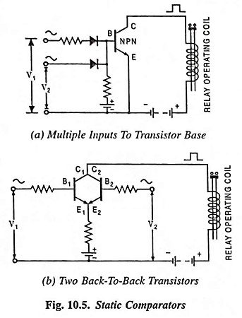
In either of the circuits shown in Fig. 10.5 (a) and 10.5 (b) current of constant magnitude flows in the collector circuit only when the input ac quantities are simultaneously positive; a relay in the collector circuit will pick up when the overlap angle exceeds a certain value, i.e., when the mean dc level in the collector circuit exceeds the relay pick up as a consequence of phase coincidence.
5. Hall Effect Relays
When a conductor is kept perpendicular to the magnetic field and a direct current is passed through it, it results in an electric field perpendicular to the directions of both the magnetic field and current with a magnitude proportional to the product of the magnetic field strength and current. The voltage so developed is very small and it is difficult to detect it. But in some semiconductors such as indium arsenide, indium antimonide, indium phosphate, germanium etc., this voltage is enough for measurement with a sensitive moving coil instrument. This phenomenon is called the Hall effect.
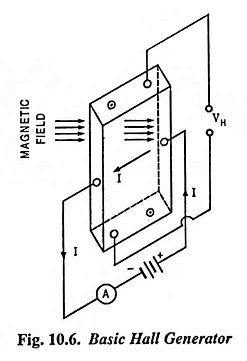
Figure 10.6 illustrates the basic Hall generator where the Hall crystal in the form of a slab is connected to a battery so that a current I flows through the slab in the manner shown in the figure and the magnetic field is applied so that it is perpendicular to the slab of the Hall crystal. A potential difference VH, called the Hall voltage, is developed between the top and bottom of the slab. The magnitude of this voltage is proportional to the product of strength of the magnetic field and current.

then Hall voltage VH is given as
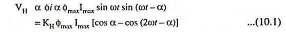
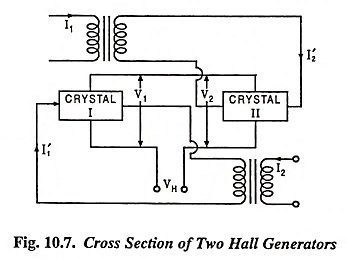
In the above expression the first term on the right hand side is a dc voltage proportional to the vectorial product of the two inputs—flux and current, the second term is an ac voltage of double frequency. The double frequency term can be eliminated by cross-connecting two Hall generators, as illustrated in Fig. 10.7 where two input signals are the sinusoidal ac currents I1 and I2.
If currents I1 and I2 are given as

Flux through crystals I and II will be Φ1 α I1 and Φ2 α I2
and current through the crystals will be

Two crystals I and II are connected in such a way that their output voltages are in opposition. So the output voltage will be
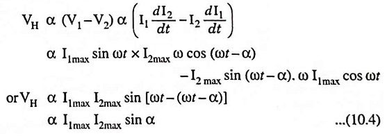
The device thus acts as a pure phase comparator. A telephone type relay can be directly operated from the Hall voltage. Hall device is much simpler in construction and does not require auxiliary dc supply while the transistorized circuits require about 10V dc supply.
Because of the high cost of Hall element, low output and large temperature error, this comparator is normally not used.
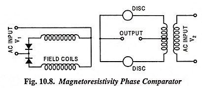
6. Gauss Effect Relays
The resistivity of some metals and semiconductors at low temperature changes when exposed to the magnetic field. This phenomenon is called the magnetoresistivity or Gauss effect. This effect depends upon the ratio of depth to width and increases with the increase in this ratio. In some metals, this effect is noticeable at room temperature, as in case of bismuth. Magnetoresistors are sensitive to the magnetic field strength and not to the rate of variation. Indium antimonide and indium asrenide are more sensitive in comparison to bismuth or mumetal.
If one ac voltage V1 develops a magnetic field through the crystal in the form of disc having large diameter and another ac voltage V2 sends a current radially through the disc, then the current will be proportional to V1V2 cos θ where θ is the angle between the two voltages V1 and V2 i.e., current is maximum when the two voltages are in phase and zero when they are in quadrature. Such a relay is considered better than Hall effect relay because of simpler construction and circuitry [Fig. 10.8]. Polarizing current is not required and output is relatively higher. But its use in static relays is limited because of high cost of crystal.