What is Sampling Oscilloscope?:
An ordinary Sampling Oscilloscope has a B.W. of 10 MHz. The HF performance can be improved by means of sampling the input waveform and reconstructing its shape from the sample, i.e. the signal to be observed is sampled and after a few cycles the sampling point is advanced and another sample is taken. The shape of the waveform is reconstructed by joining the sample levels together. The sampling frequency may be as low as 1/10th of the input signal frequency (if the input signal frequency is 100 MHz, the bandwidth of the CRO vertical amplifier can be as low as 10 MHz). As many as 1000 samples are used to reconstruct the original waveform.
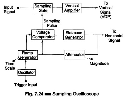
Figure 7.24 shows a block diagram of a sampling oscilloscope. The input waveform is applied to the sampling gate. The input waveform is sampled whenever a sampling pulse opens the sampling gate. The sampling must be synchronized with the input signal frequency. The signal is delayed in the vertical amplifier, allowing the horizontal sweep to be initiated by the input signal. The waveforms are shown in Fig. 7.25.
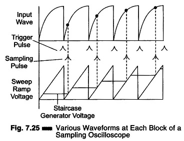
At the beginning of each sampling cycle, the trigger pulse activates an oscillator and a linear ramp voltage is generated. This ramp voltage is applied to a voltage comparator which compares the ramp voltage to a staircase generator. When the two voltages are equal in amplitude, the staircase advances one step and a sampling pulse is generated, which opens the sampling gate for a sample of input voltage.
The resolution of the final image depends upon the size of the steps of the staircase generator. The smaller the size of the steps the larger the number of samples and higher the resolution of the image.