Resistance Temperature Detector (RTD):
Resistance Temperature Detector (RTD) commonly use platinum, nickel or any resistance wire whose resistance varies with temperature and which has a high intrinsic accuracy. They are available in many configuration and sizes; as shielded or open units for both immersion and surface applications.
The relationship between temperature and resistance of conductors in the temperature range near 0°C can be calculated using the equation
![]()
where
- Rt = resistance of conductor at temperature t°C
- Rref = resistance of the reference temperature, usually 0°C
- α = temperature coefficient of resistance
- Δt = difference between operating and reference temperature
Almost all metals have a positive temperature coefficient (PTC) of resistance, so that their resistances increases with increase in temperature. Some materials, such as Carbon and Germanium have a negative temperature coefficient (NTC) of resistance.
A high value of ‘α’ is desired in a temperature sensing element, so that sufficient change in resistance occurs for a relatively small change in temperature. This change in resistance (ΔR) can be measured with a Wheatstone’s bridge which can be calibrated to indicate the temperature, that caused the resistance change rather than the resistance itself. The sensing element of the RTD is selected according to the intended applications.
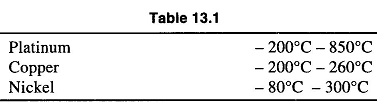
Resistance Temperature Detector are wire-wound resistance with moderate resistance and a PTC of resistance. Platinum is the most widely used resistance wire type because of its high stability and large operating range. However, Nickel and Copper are also used in RTDs. The temperature ranges for various resistance wire are given in Table 13.1.
Platinum RTDs provide high accuracy and stability. They have the following advantages:
- Linearity over a wide operating range.
- Wide operating range
- Higher temperature operation
- Better stability at high temperature
Disadvantages of Resistance Temperature Detector:
- Low sensitivity
- It can be affected by contact resistance, shock and vibration
- Requires no point sensing
- Higher cost than other temperature transducers
- Requires 3 or 4 wire for its operation and associated instrumentation to eliminate errors due to lead resistance
RTD’s are not adaptable to applications requiring fast response or small area temperature sensing. Measurement of temperature using RTD is done after proper calibration that involves conversion of resistance value to temperature.
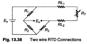
Most RTD instruments use a Wheatstone’s Bridge or its modified version. The RTD and its leads are connected in one of its arms. This bridge is essentially a resistance measuring device which converts the resistance of the RTD into an electrical signal that is used for monitoring or controlling temperature. The basic Wheatstone’s Bridge with a two wire RTD connected is as shown in Fig.13.38.
where
- Es = Supply voltage
- Eo = output voltage used for monitoring or controlling temperature
- R1 – R2 and R3 = fixed value resistors
- RT = resistance of temperature sensing element in RTD
- RL1 and RL2 = resistance of the two leads connected in the RTD element
The value of RT at the control point or at the mid point of the temperature range to be monitored will influence the arm resistors R1, R2 and R3. Also, these values must be selected to limit bridge currents to avoid self-heating of RTD or bridge resistors. For achieving high accuracy, the bridge must be stable and insensitive to ambient temperature variations.
If the value of the lead resistance is small and also the variation of the lead resistance is small over the temperature range as compared to that of the RTD values, then the errors introduced by the lead resistance are not significant.
However, the errors introduced by long leads are significant and can be reduced by using thick lead wire. As an effective method to obtain a high degree of accuracy, it is desirable to use lead resistance compensation techniques or lead error elimination technique such as three wire and four wire RTD connections.
Two lead Resistance Temperature Detector which is lower in cost, is normally used when the lead resistance is low in comparison with Ohms/°C resistance change of the RTD or when lead wire resistance compensation is provided in the instrumentation.
Three Lead Wire RTD:
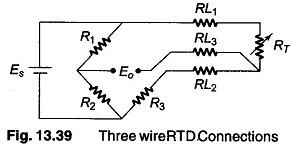
Three lead wire RTD, offers a practicable method for lead wire compensation that is sufficiently accurate for most industrial applications. The bridge circuit automatically compensates resistance change due to ambient temperature change, which is the input to the instrumentation. A three lead Resistance Temperature Detector connected to a Wheatstone Bridge circuit is as shown in Fig. 13.39.
This bridge circuit is used whenever lead wire resistance is significant in comparison with Ohms/°C sensitivity of the RTD elements, for example, the 10 Ω copper RTD element used in the industry should always have three leads. Other commonly used RTD elements such as 100 Ω platinum and 120 Ω Nickel may also need such compensation when lead wire resistance is significant.
Referring to Fig. 13.39, it can be seen that one of the RTD leads L1 is in the arm of the bridge with RT and a second lead L2 is in the adjacent arm with R3.
When the bridge is balanced, all the bridge arm resistance are equal, hence same current flows in all the bridge arms. The same current flows through both these leads L1 and L2 under balance conditions, therefore the voltage drop across them will be identical and being in the adjacent arms will effectively cancel out. Hence the effect of the lead wire is eliminated.
The third lead L3, is connected in the output circuit of the bridge and has no effect on the bridge ratios or balance. Hence when the bridge is balanced no current flows through L3 and therefore has no effect on the bridge balance. This method gives very good accuracy if the lead resistances are matched.
Four Lead RTD Connection:
The three lead RTD gives sufficient accuracy for most of the industrial applications. However, when a higher degree of accuracy and precision is required, a four lead RTD connection is used.
The four lead RTD is the most expensive type, especially when long four wire extension leads are needed to connect to the instrumentation. However the four lead Resistance Temperature Detector can offer the greatest accuracy if the instrumentation is properly designed. Four lead RTDs are widely used in laboratory work, where highest precision is required.
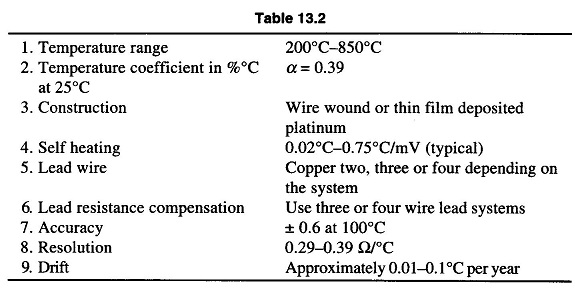
To select a 100 Ω Platinum RTD, the information given in Table 13.2 is helpful.