Programming Techniques in Microprocessor 8085:
We have seen the instruction set of 8085 and some simple assembly language programs using it. We know that, the program is an implementation of certain logic by executing group of instructions. To implement program logic we need to take help of some common Programming Techniques in Microprocessor 8085 such as looping, counting, indexing and code conversion.
In this section, we are going to study how to implement these Programming Techniques in Microprocessor 8085 assembly language and some programming examples using them.
1. Looping, Counting and Indexing:
Before going to implement these Programming Techniques in Microprocessor 8085, we get conversant with these techniques and understand the use of them.
Looping : In this Programming Techniques in Microprocessor 8085, the Program is instructed to execute certain set of instructions repeatedly to execute a particular task number of times. For example, to add ten numbers stored in the consecutive memory locations we have to perform addition ten times.
Counting : This technique allows programmer to count how many times the instruction/set of instructions are executed.
Indexing : This Programming Techniques in Microprocessor 8085 allows programmer to point or refer the data stored in sequential memory locations one by one. Let us see the program loop to understand looping, counting and indexing.
The Program loop is the basic structure which forces the processor to repeat a sequence of instructions. Loops have four sections.
- Initialization section.
- Processing section.
- Loop control section
- Result section.
Flowchart:

- The initialization section establishes the starting values of
- loop counters for counting how many times loop is executed,
- address registers for indexing which give pointers to memory locations and
- other variables
- The actual data manipulation occurs in the processing section. This is the section which does the work.
- The loop control section updates counters, indices (pointers) for the next iteration.
- The result section analyzes and stores the results.
Note : The processor executes initialization section and result section only once, while it may execute processing section and loop control section many times. Thus, the execution time of the loop will be mainly dependent on the execution time of the processing section and loop control section. The flowchart 1 shows typical Program loop. The processing section in this flowchart is always executed at least once. If you interchange the position of the processing and loop control section then it is possible that the processing section may not be executed at all, if necessary. Refer flowchart 2.
2. Timers:
In the real time applications, such as traffic light control, digital clock, process control, serial communication, it is important to keep a track with time. For example in traffic light control application, it is necessary to give time delays between two transitions. These time delays are in few seconds and can be generated with the help of executing group of instructions number of times. This software timers are also called time delays or software delays. Let us see how to implement these time delays or software delays.
As you know microprocessor system consists of two basic components, Hardware and software. The software component controls and operates the hardware to get the desired output with the help of instructions. To execute these instructions, microprocessor takes fix time as per the instruction, since it is driven by constant frequency clock. This makes it possible to introduce delay for specific time between two events. In the following section we will see different delay implementation techniques.
2.1 Timer Delay Using NOP Instruction:
NOP instruction does nothing but takes 4T states of processor time to execute. So by executing NOP instruction in between two instructions we can get delay of 4 T-state
![]()
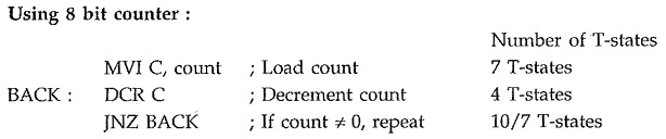
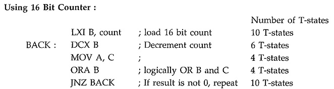
2.2 Timer Delay Using Counters:
Counting can create time delays. Since the execution times of the instructions used in a counting routine are known, the initial value of the counter, required to get specific time delay can be determined.
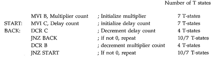
2.3 Timer Delay Using Nested Loops:
In this, there are more than one loops. The innermost loop is same as explained above. The outer loop sets the multiplying count to the delays provided by the innermost loop.
3. Code Conversion:
This Programming Techniques in Microprocessor 8085 is to translate a number represented using one coding system to another. For example,, when we accept any number from the keyboard it is in ASCII code. But for processing, we have to convert this number in its hex equivalent. The code conversion involves some basic conversions such as
- BCD to Binary conversion
- Binary to BCD conversion
- BCD to seven segment code conversion
- Binary to ASCII conversion and
- ASCII to binary conversion
BCD to Binary Conversion:
We are more familar with the decimal number system. But the microprocessor understands the binary/hex number system. To convert BCD number into its binary equivalent we have to use the principle of positional weighting in a given number.
Binary to BCD Conversion:
We know that microprocessor processes data in the binary form. But when it is displayed, it is in the BCD form. In this case we need binary to BCD conversion of data. The conversion of binary to BCD is performed by dividing the number by the power of ten.
BCD to Seven Segment Conversion:
Many times 7-segment LED display is used to display the results or parameters in the microprocessor system. In such cases we have to convert the result or parameter in 7-segment code. This conversion can be done using look-up technique. In the look-up table the codes of the digits (0-9) to be displayed are stored sequentially in the memory. The conversion program locates the code of a digit based on its BCD digit. Let us see the Program for BCD to common cathode 7-segment code conversion.
Binary to ASCII Code Conversion:
The ASCII Code (American Standard Code for Information Interchange) is commonly used for communication. In such cases we need to convert binary number to its ASCII equivalent. It is a seven bit code. In this code number 0 through 9 are represented as 30 through 39 respectively and letters A through Z are represented as 41H through 5AH. Therefore, by adding 30H we can convert number into its ASCII equivalent and by adding 37H we can convert letter to its ASCII equivalent. Let us see the Program for binary to ASCII code conversion.
ASCII Code to Binary Conversion:
It is exactly reverse process to binary to ASCII conversion. Here, if ASCII code is less than 3AH then 30H is subtracted to get the binary equivalent and if it is in between 41H and 5AH then 37H is subtracted to get the binary equivalent of letter (A-F).