Phase Comparison Carrier Protection:
The phase comparison pilot-relaying operates on the principle of comparing the phase position of the currents at the two ends of the protected section. The Phase Comparison Carrier Protection of these currents is made over carrier channels. During normal conditions or through faults the currents entering the line at one end, differ in phase-by approximately 180° from those entering the line at the other end. Therefore, the relaying quantities at the two ends are about 180° apart. However, during an internal fault the relaying quantities’ at the two ends have a phase difference of nearly 0°.
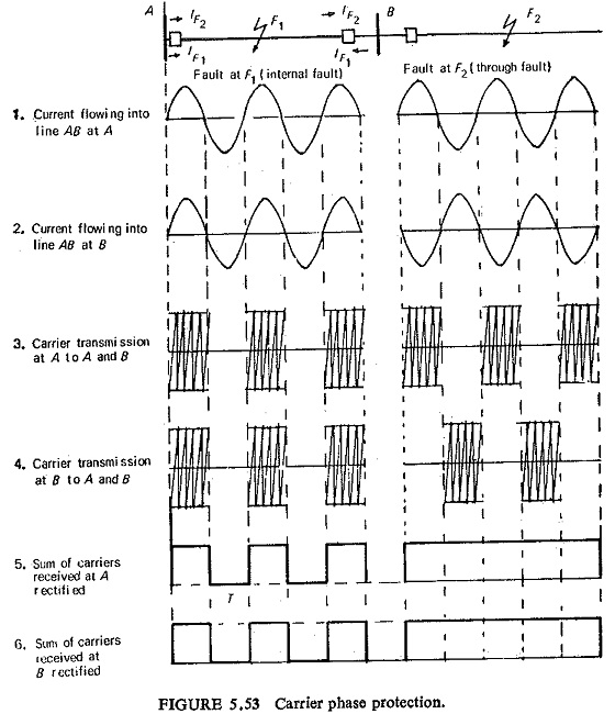
Figure (5.53) illustrates the method of Phase Comparison Carrier Protection. It can be seen that a carrier signal is transmitted only during. the positive half cycle of the current wave.
The current flowing into the line section at breakers A and B is shown in positions 1 and 2 both for internal and through faults separately. The carrier transmission at A and B is shown in positions 3 and 4 for the two fault locations. The carrier transmissions, at A from A and from B are added and rectified to give an output signal as shown in position 5. When the signal has a zero value for a specified time as at T, the circuit breaker is tripped by an auxiliary equipment. Whereas for a nonzero value of the signal throughout the entire cycle the breaker is prevented from tripping.
Similar behavior at breaker B results in a trip signal for fault at F1 and no signal to the trip circuit for fault at F2 as shown in position 6. So for fault between A and B both the breakers at A and B trip, whereas for fault outside A-B none of the breakers at A and B trip.
It may be noted that with this phase comparison arrangement, a trip signal is available with a fault in the line section, but none is available if the fault is exterior. In the event of failure of the carrier equipment, the affected line section will be opened even though no fault exists on it.
Scheme of Phase Comparison Carrier Protection:
Phase Comparison Carrier Protection relays require a single phase relaying quantity obtained by linear combination of line currents by some filter network or some sequence network. The summation CTs provide a single phase representative value, but has the disadvantage of blind spots in summation CT configuration. By blind spots is meant absence of an output under certain types of internal faults. To overcome this difficulty, the network output normally consists of a combination of positive and negative sequence currents of the type (I1 – NI2) where N is adjustable or fixed at 4 or 5.
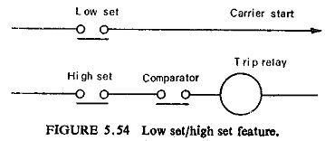
It must be ensured that the carrier system starts at minimum fault condition and at the same time it does not operate at maximum load conditions. Response to the amplitude only of the negative sequence signal ‘ is sufficient for unbalanced faults, whereas response to both amplitude and rate of increase of positive sequence output is necessary for balanced faults. Two settings for each of the positive and negative sequence starting arrangements are provided a low set and a high set. A low set for starting relay to control transmission and a high set starting relay to control the tripping circuit as shown in Fig. (5.54). One basic reason for employing starting devices is to use the carrier equipment under fault conditions so that the same equipment could be used for communication purposes during healthy conditions. Figure (5.55) shows a schematic diagram of the basic scheme of Phase Comparison Carrier Protection.
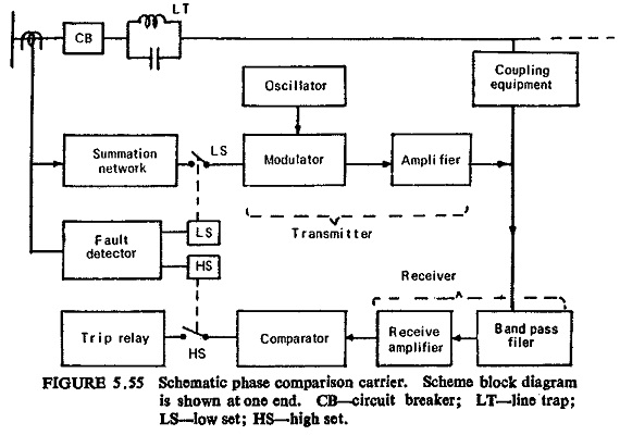
The three secondary currents from the CTs are fed into a summation network which produces a single 50 Hz output signal, which is fed into a modulator. The modulator is also fed with a carrier signal from the oscillator and thus the combination produces a modulated carrier signal. This signal being relatively at low power level is amplified in the power amplifier so that the power level is about 10 to 20 W. It is then fed to the power line via coupling equipment for transmission to the remote, end. Similarly the carrier signal is received via coupling equipment, and separated from other carrier signals by means of a narrow band pass filter, after which it is amplified in the receive amplifier and then supplied to the comparator. The receive signal at this stage contains both the remote signal and the local signal, so that the comparator compares the phase angle of the currents at the two ends of the line by looking at the sum of the carrier signals. The output of the comparator is fed to the tripping relay.
In general the comparator is a vacuum tube equipment, which for purposes of understanding is represented as a single tube as in Fig. (5.56).
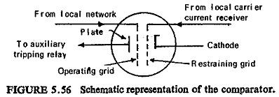
When voltage of positive polarity is impressed on the operating grid by the local network, the tube conducts if voltage of negative polarity is not concurrently impressed on the restraining grid by the local carrier current receiver, by virtue of the carrier current received from the other end of the line. When the tube conducts, an auxiliary tripping relay picks up and trips the local breaker. Positive polarity is impressed on the operating grid of the local comparator during the negative half cycle of the network output when the local transmitter is idle. Therefore, the local transmitter cannot block local tripping. The voltage from the carrier current receiver impressed on the restraining grid makes the tube nonconducting, whether the operating grid is energized or not, whenever carrier current is being received. The comparator could also be a transistorized circuit.
So far we have assumed that the phase difference between the currents at both ends of the protected section during an internal fault is zero. However in actual practice this phase difference Φ can vary over wide limits, depending upon (i) the phase angle between the emfs at the terminals of the protected section, (ii) the value of the line impedance on either side of the fault, and (iii) the errors in CTs, etc.
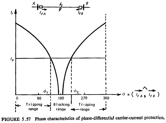
It is therefore clear that for Φ = 0° (i.e. internal fault) the magnitude of the current flowing through the control relay is maximum and the protection operates, whereas for Φ = 180° (i.e. external fault) this current is zero and the protection remains inoperative. In Fig. (5.57) the value of the current in the control relay versus the phase difference between the relaying quantities at the opposite ends of the protected section is shown. If the pickup current of the relay is Ip reliable tripping occurs for values of Φ either less than Φ1 or greater than Φ2 (Φ1≥Φ≥Φ2). The value of the pickup current is so adjusted that reliable tripping occurs for Φ≤120° to 140°.
Under power swings and out-of-step operation the relaying quantities at both ends of the protected section have a phase difference of nearly 180°. Owing to the inherent characteristics of the phase comparison protection, it will not respond to such operating conditions.
Amplitude comparison techniques similar to the one used in differential relaying are not used in the carrier relaying because of the fact that in a carrier channel the attenuation varies with atmospheric conditions. The length of the pilot wire channel that can be used is limited by the phase shift due to the capacitance between the wires; similarly the length of the transmission line that can be protected by Phase Comparison Carrier Protection is limited by phase shifts caused by the following factors :
- The propagation time, i.e. the time taken by the carrier signal to reach the other end of the line (up to 0.1° per mile).
- The response time of the band pass filter (about 5°).
- The capacitance phase shift of the transmission line (up to 10°).