Parametric Amplifier Types:
The basic Parametric Amplifier Types have already been discussed in detail, but several others also exist. They differ from one another in the variable reactance used, the bandwidth required and the output frequency (signal or idler). Various other characteristics of Parametric Amplifier Types must also now be discussed, such as practical circuits, their performance and advantages, and lastly the important noise performance.
Amplifier Types:
When classifying parametric amplifiers, the first thing to decide is the device whose parameter will be varied. This is now always a varactor, whose capacitance is varied, but u variable inductance can also be used. Indeed, the first Parametric Amplifier Types, using an RF magnetic field to pump a small ferrite disk. Such amplifiers are no longer used, mainly because their noise figures do not compare with those available from varactor amplifiers.
Parametric Amplifier Types (or paramps) may be divided into two main groups; negative-resistance and positive-resistance. The upper-side band up-converter is the only useful member of the second group. Its output is taken at the idler frequency fi = fp + fs, and the pump frequency is less than signal frequency. The resulting amplifier has low gain, but a high pumping frequency is not required. This amplifier is most useful at the highest frequencies, for which it was developed.
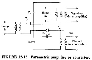
Negative-resistance paramps are either straight-out amplifiers (fo = fi) or lower-sideband converters. If the output is taken at the idler frequency, we have the two-port lower-sideband up-converter. Such a circuit is shown in Figure 12-15. The lower-sideband down-converter is in the same category. The output is still taken at the idler frequency, but this is now lower than the signal frequency. Both these amplifiers are nondegenerate.
The (straight-out) amplifier may be degenerate or not, depending on whether pump frequency is twice signal frequency. The two types share the disadvantage of being one-port (two-terminal) amplifiers. The nondegenerate amplifier is the one in which the pump frequency is (much) higher than the signal frequency but is quite unrelated to it. The circuit of Figure 12-15 also applies here.
Any paramp can belong to one of two broad classes. First there are narrowband amplifiers using a varactor diode that is part of a tuned circuit. Paramps can be wideband, in which case a number of diodes are used as part of a traveling-wave structure.
Narrowband Amplifiers:
The negative-resistance Parametric Amplifier Types almost always used in practice. The most commonly used types are the nondegenerate one-port amplifier and the two-port lower-sideband up-converter, in that order. The circuit of Figure 12-15 could be either type, depending on where the output is taken. The one-port amplifier may suffer from a lack of stability and low gain due mainly to the fact that the output is taken at the input frequency. On the other hand, the pump power is low and so is noise, and the amplifier can be made small, rugged and inexpensive.
Undoubtedly the fundamental drawback of this amplifier, as it stands, is that the input and output terminals are in parallel, as shown in Figure 12-15. This applies to all two-terminal amplifiers. If such an amplifier is followed by a relatively noisy stage such as a mixer, then the noise from the mixer, present at the output of the parametric amplifier, will find its way to the amplifier’s input. therefore be re-amplified, and the noise performance will suffer.
In order to overcome this difficulty, a circulator is used. The four-terminal version of the Y stripline circulator is particularly suitable. The arrangement is then identical with the paramp replacing the tunnel diode amplifier shown there. The output of the antenna feeds the parametric amplifier, whose output can go only to the mixer. Any noise present at the input of the mixer can be coupled neither to the paramp nor to the antenna; it goes only to the matched termination. The circulator itself can generate some noise, but this may be reduced with proper techniques (such as cooling).
If the output is taken at the idler frequency (in Figure 12-15), a two-port lowersideband up-converter results, for which a circulator is not required. It has been shown that this type of amplifier is capable of a very low noise figure if fi/fs is in excess of about 10. In fact, as this ratio increases, noise figure is lowered, but there are two limitations. The first is the complexity and/or lack of suitably powerful pump sources at millimeter wavelengths, which means that this amplifier is unlikely to be used above X band. The second limitation is the very narrow bandwidth available for minimum noise conditions. The result of all these considerations is that the nondegenerate one-port amplifier (with circulator) is most likely to be used for low-noise narrowband applications.
Traveling-wave Diode Amplifiers:
All the Parametric Amplifier Types so far described use cavity or coaxial resonators as tuned circuits. Since such resonators have high Q’s and therefore narrow bandwidths; parametric amplifiers using them are anything but broadband; the available literature does not describe any such amplifier exceeding a bandwidth of 10 percent. However, it is possible to use traveling-wave structures for parametric amplifiers to provide bandwidths as large as 50 percent of the center frequency, with other properties comparable to those of narrowband amplifiers.
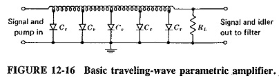
As shown in Figure 12-16, a typical traveling-wave amplifier employs a multistage low-pass filter, consisting of either a transmission line or lumped inductances, with suitably pumped shunt varactor diodes providing the shunt capacitances. The signal and pump frequencies are applied at the input end of the circuit, and the required output is taken from the other end. If the filter is correctly terminated at the desired output frequency, this will not be reflected back to the input, and thus unilateral operation is obtained, even for a negative-resistance amplifier without a circulator. The only real disadvantage is a lower gain than with narrowband amplifiers.
In order to obtain useful amplification, the pump, signal and idler frequencies must all fall within the bandpass of the filter, whereas the sum of the signal and the pump frequencies must fall outside the bandpass. This suggests that the pump frequency must not be very much higher than the signal frequency, or filtering will be difficult. As the wave progresses along the filter (lumped or transmission-line), the signal and idler voltages grow at the expense of the pumping signal. Although this power conversion becomes more complete as the length of the line is increased, the growth rate reduces. Maximum gain is achieved for a certain optimum length of line (or number of lumped sections), particularly as ohmic losses increase with the length.
Noise Cooling:
The noise figures of practical parametric amplifiers are extremely low, a very close second only to those of cooled multilevel masers, The reason for such low noise is that the variable transconductance used in the amplifying process is reactive, rather than resistive as in the more orthodox amplifiers. Once noise contributions due to associated circuitry (such as the circulator) have been minimized, the only noise source in the parametric amplifier is the base resistance, sometimes called the spreading resistance. This being the case, it seems that cooling the paramp and associated circuitry should have the effect of lowering its noise considerably.
Those paramps that are not operated at room temperature (290 K, or 17°C, is considered standard) may be cooled to about 230 K by using Peltier thermoelectric cooling. The next step is to use cryogenic cooling with liquid nitrogen (to 77 K) or with liquid helium (4.2 K). Cryogenic apparatus is outside the scope of this book, although one system.
It must be emphasized that cooling is used with some Parametric Amplifier Types in an attempt to improve their performance; it is neither compulsory nor always employed. As a matter of fact, although the noise temperature improvement which results from cooling is significant, it is not as great as might be expected. It would appear that the spreading resistance is increased as temperature is lowered, perhaps because of a decrease in the mobility of the varactor’s charge carriers. The point is uncertain, however, because measurements at extremely low temperatures are rather difficult to make.
Cryogenic cooling tends to be bulky and expensive, and consequently the current trend is away from cryogenically cooled amplifiers, except for the most exacting applications, as in radiotelescopes, some satellite earth stations, and space communication terminals. Thus applications requiring very good but not critical noise figures, including portable earth stations, are likely to use Peltier cooled or uncooled paramps. The other current design feature is the use of solid-state (especially Gunn) oscillators for pumps, although a lot of existing parametric amplifiers still use klystrons or even varactor chains.
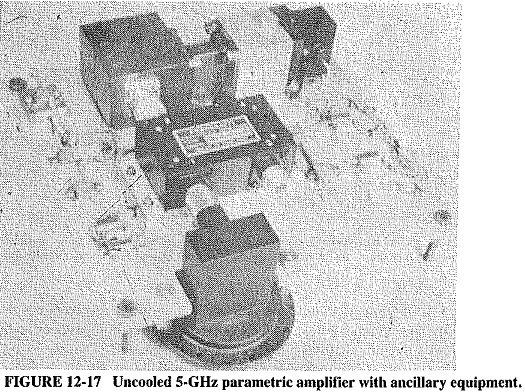
The Ferranti parametric amplifier of Figure 12-17 is uncooled. In the figure, terminal 1 is the RF input, 2 is the pump input, 3 the RF output and 4 the connection phint for temperature stabilizing equipment. The circulator is behind the paramp box, which measures approximately 70 X 45 X 25 mm. The Gunn diode pump source is located next to the circulator, together with its cavity and thermal stabilizer. The panel has its own dc supply and simply plugs into the mains. Two diodes are connected back-to-back in a coaxial circuity using a system pioneered by the firm. The varactors in the paramp are high-quality, high-frequency GaAs ones.
Performance Comparisons:
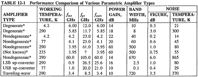
There are so many different Parametric Amplifier Types and temperatures at which they may be used that tabular comparison is considered the most convenient. Accordingly, Table 12-1 compares a number of typical paramps; note the degradation in noise figure with increased temperature and/or operating frequency. Note also the lower bandwidth of converters as compared with nondegenerate one-port amplifiers, while the traveling-wave amplifier has by far the greatest percentage bandwidth.
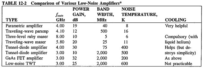
The comparison in Table 12-2 is between paramps and other low-noise amplifiers. Note that the best, rather than typical, performances are included in Table 12-2.