Megger Circuit Diagram:
Another common method of measuring resistances above 50 M Ω is the Megger Circuit Diagram (megaohmmeter) shown in Fig. 10.23(a). This instrument is used to measure very high resistances, such as those found in cable insulations, between motor windings, in transformer windings, etc.
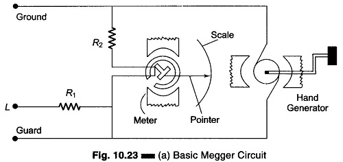
Construction and Working Principles:
Normal (shop) VOMs do not provide accurate indications above 10 MΩ because of the low voltage used in the ohmmeter circuit. Some laboratory test meters have a built-in ohmmeter with a high voltage power supply. The high voltage permits accurate high resistance measurement, but such meters are usually not portable. The Megger is essentially a portable ohmmeter with a built-in high voltage source. The Megger Circuit Diagram, shown in Fig. 10.23(b), has two main elements, a magnet-type dc generator to supply current for making measurements, and an ohmmeter which measures the resistance value. The generator armature is turned by a hand crank usually through step up gears, to produce an output voltage of 500 V. When the crank is turned, the gears turn the generator at high speed to generate an output voltage that may be 100, 500, 1000, 2500 or 5000 V, depending on the model.
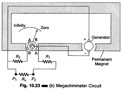
The meter used differs slightly from the standard D’Arsonval movement, in that it has two windings. One windings is in series with the reference R2 across the output of the generator, and is wound in such a way as to move the pointer towards the high resistance end of the scale when the generator is in operation. The other winding coil (A) and resistance R1 are connected in series between the negative pole of the generator and the line terminal. This winding is so wound that when current flows through it from the generator, it tends to move the pointer towards the zero end of the scale. The two coils are mounted on the same shaft but at right angles to each other. Current is fed to both the coils by means of flexible connections that do not hinder the rotation of the element.
Coil A is the current coil with one terminal connected to the negative output and the other connected in series with R1 to the test Lead P2. Test lead P1 is connected to the generator positive output. When the unknown resistance Rx is connected across P1 and P2, current flows from the generator through coil A, resistances R1 and Rx. The value of R1 is so chosen so as to ensure that even if the line terminals are short-circuited, the current coil A is not damaged.
Coil B is the voltage coil and is connected across the generator output through the resistance R2. If the test leads are left open, no current flows in coil A and coil B alone moves the pointer. Coil B take a position on the opposite side in the core, and the pointer indicates infinity or open.
When an extremely high resistance appears across the terminals, such as in an open circuit, the pointer reads infinity. On the other hand, when a resistance of relatively low value appears across the test points, such as when the cable insulation is wet, the current through the series winding causes the pointer to move towards zero (resistance short-circuited). However, the pointer stops at a point on the scale determined by the current through the series resistor, which in turn is governed by the value of the resistance being measured.
When an unknown resistance Rx is connected across the test leads, the current flows in coil A. The corresponding torque developed moves the pointer away from the infinity position, into a field of gradually increasing strength, until the torque fields between coils A and B are equal. Variations in the speed of the hand-cranked generator do not affect the Megaohmmeter readings, since charges in generator voltage affects both coils in the same manner.
Advantages of using Megger:
Megger Circuit Diagram may read resistances of several hundred or even thousands of megaohms. They have the advantage, as compared to an ordinary ohmmeter, of applying a high voltage to the circuit under test, and this voltage causes a current if any electrical leakage exists.