Magnetic Field Equation:
The exact description of the Magnetic Field Equation Basics is given by the Maxwell’s equations and the constitutive relationship of the medium in which the field is established. Such description apart from being highly complex is otherwise not necessary for use in electric machines wherein the fields (magnetic and electric) are slowly varying (fundamental frequency being 50 Hz) so that the displacement current can be neglected. The Magnetic Field Equation can then be described by Ampere’s law and is solely governed by the conduction current. This law is in integral form and is easily derivable from the third Maxwell’s equation (by ignoring displacement current) by means of well-known results in vector algebra. The Ampere’s law is reproduced as follows:
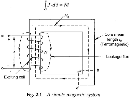
 Consider the example of a simple electromagnetic system comprising an exciting coil and ferromagnetic core as shown in Fig. 2.1. The coil has N turns and carries a constant (dc) current of i A. The Magnetic Circuits field is established in the space wherein most of the total magnetic flux set up is confined to the ferromagnetic core for reasons which will soon become obvious. Consider the flux path through the core (shown dotted) which in fact is the mean path of the core flux. The total current piercing the surface enclosed by this path is as follows:
 Hence Eq. (2.1) acquires the form
 Since N is the number of coil turns and i the exciting current in amperes, the product F= Ni has the units of ampere-turns (AT) and is the cause of establishment of the Magnetic Field Equation. It is known as the magnetomotive force (mmf) in analogy to the electromotive force (emf) which establishes current in an electric circuit. The Magnetic Circuits field intensity H causes a flux density B to be set up at every point along the flux path which is given by
 The units of flux density are weber (Wb)/m2 called tesla (T). The term μ0 is the absolute permeability of free space and has a value of
The permeability μ=μ0μr of a material medium is different from μ0 because of a certain phenomenon occurring in the material. The term μr is referred to as relative permeability of a material and is in the range of 2000-6000 for ferromagnetic materials. It is, therefore, seen that for a given H, the flux density B and, therefore, the flux over a given area
 will be far larger in the Magnetic Circuits core in Fig. 2.1 than in the air paths. Hence, it is safe to assume that the magnetic flux set up by mmf Ni is mainly confined to the ferromagnetic core and the flux set up in air paths is of negligible value. The flux set up in air paths is known as the leakage flux as if it leaks through the core; some of the leakage flux paths are shown chain-dotted in Fig. 2.1. There is no way to avoid magnetic leakage as there are no magnetic insulators in contrast to electric insulators which confine the electric current to the conductor for all practical purposes. The effect of the leakage flux is incorporated in machine models through the concept of the leakage inductance.
The direction of field intensity is H and so the direction of flux Φ is determined from the Right Hand Rule (RHR). It is stated as:
Imagine that you are holding a current carrying conductor in your right hand with the thumb pointing in the direction of current. Then the direction in which the fingers curl gives the direction of flux. In case of a coil you imagine that you are grasping the coil in right hand with the thumb in the direction of current; then the fingers curl in the direction of flux.
The reader may apply RHR to the exciting coil in Fig. 2.1 to verify the direction of flux as shown in the figure. The Magnetic Field Equation intensity H is tangential to a flux line all along its path, so that the closed vector integration in Eq. (2.2) along a flux-line reduces to closed scalar integration, i.e. With the assumption of negligible leakage flux, the flux piercing the core cross-section at any point remains constant. Further, from the consideration of symmetry it immediately follows that the flux density over straight parts of the core is uniform at each cross-section and remains constant along the length; such that H is constant along the straight parts of the core. Around the corners, flux lines have different path lengths between magnetic equipotential planes (typical ones being ab and cd shown in Fig. 2.1) so that H varies from a high value along inner paths to a low value along outer paths. It is reasonable to assume that H shown dotted along the mean path will have the same value as in straight parts of the core (this mean path technique renders simple the analysis of Magnetic Circuits of machines and transformers).
It has been seen previously that the Magnetic Field Equation intensity along the mean flux path in the core can be regarded constant at Hc. It then follows from Eq. (2.4) that If one now imagines that the exciting current i varies with time, Eq. (2.6) would indicate that Hc will vary in unison with it. Such fields are known as quasi-static fields in which the field pattern in space is fixed but the field intensity at every point varies as a replica of the time variation of current. This simplified field picture is a consequence of negligible displacement current in slowly-varying fields as mentioned earlier. In a quasi-static field, the field pattern and field strength at a particular value of time-varying exciting current will be the same as with a direct current of that value. In other words, a field problem can be solved with dc excitation and then any time variation can be imparted to it.
Now, the core flux density is given by,
![]() and core flux (assumed to be total flux) is given by,
and core flux (assumed to be total flux) is given by,
 where Ac = cross-sectional area of core and flux in the limbs is oriented normal to cross-sectional area. Then from Eq. (2.6)
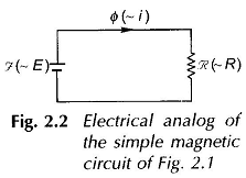
It is, therefore, seen that by certain simplifying assumptions and field symmetries, it has been possible to lump the distributed magnetic system into a lumped magnetic circuit described by Eq. (2.7) which is analogous to Ohm’s law in dc circuits. The electrical circuit analog of the magnetic system (now reduced to a magnetic circuit) is shown in Fig. 2.2 Fig. 2 2 wherein (mmf) is analogous to E (emf), R (reluctance) is analogous to R (resistance) and Φ (flux) is analogous to i (current). The analogy though useful is, however, not complete; there being two points of difference:
- magnetic reluctance is nondissipative of energy unlike electric resistance,
- when in time-varying, the magnetic circuit still remains resistive as in Fig. 2.2, while inductive effects are bound to appear in an electric circuit.
This is because there is no time-lag between the exciting current and the establishment of magnetic flux (quasi-static field). The lumped magnetic circuit and its electrical analog are useful concepts provided the permeability (μ) of the core material and, therefore, the core reluctance is constant as is tacitly assumed above. This, however, is not the case with ferromagnetic materials, but when air-gaps are involved, the assumption of constant reluctance is generally valid and leads to considerable simplicity in magnetic circuit analysis.
