Types of Magnetic Leakage Flux in Induction Motor:
The Magnetic Leakage Flux in Induction Motor is that flux which links only the stator or only the rotor windings. Because of the presence of air-gap in the magnetic circuit of machines, the leakage in these is quite significant and cannot be neglected in analysis as could be done in the case of transformers. The leakage in machines falls into the following two broad categories:
- Leakage in main poles, and
- Leakage in armature.
Leakage in Main Poles:
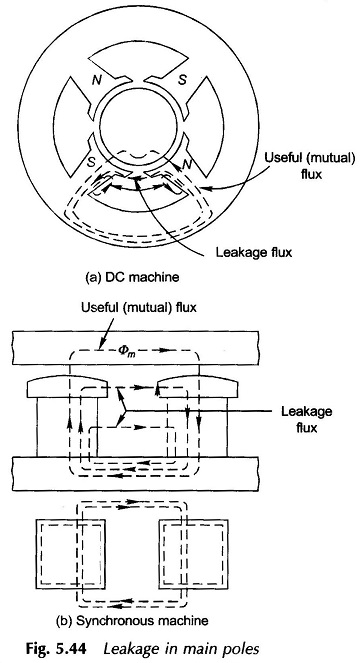
The main poles of a dc machine and that of a synchronous machine are excited by means of dc to produce a steady properly distributed flux density; the chief difference between the two being that while the poles of a dc machine form the stator and that of a synchronous machine are located on rotor. The useful flux is that flux which coming from the main poles crosses the air-gap and enters the armature. Some of the flux leaks through via two typical paths indicated in Fig. 5.44(a) without entering the armature. This then constitutes the Magnetic Flux Leakage whose only effect is to increase the flux density in the roots of the poles without contributing to useful flux and therefore must be accounted for in the magnetic circuit design of the machine. Similar leakage takes place in the poles of a synchronous machine as shown in Fig. 5.44(b).
Leakage in Armature:
The complexity of identifying the leakage paths in the wound armature arises from the fact that the winding is distributed and the armature surface slotted. The total leakage flux of the armature can be divided into several components identified in the following.
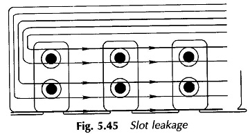
Slot leakage:
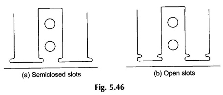
This is the flux which follows the path from tooth to tooth across the slots as shown in Fig. 5.45 and in the process links stator/rotor windings only. It is observed that the path of the slot-leakage flux is perpendicular to that of the main flux, which passes radially down the teeth, and a very small part of it straight down the slots. It is further to be noticed that a smaller amount of Magnetic Leakage flux links the bottom conductors in slots than the top conductors. The slot leakage is very much dependent upon the shape of slots. It is larger in semi-closed slots (Fig. 5.46(a)) used in induction machines, because of narrow (low reluctance) slot opening, compared to open slots (Fig. 5.46(b)) used in synchronous and dc machines.
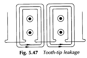
Tooth-tip leakage:
This flux follows the path from the tip of one tooth to the adjoining one enclosing all the conductors in the slot as shown in Fig. 5.47. This type of Magnetic Leakage Flux in Induction Motor is larger for larger stator to rotor air-gap as more area for the leakage flux is available. Therefore, the tooth-tip leakage is smaller in induction machines with a narrow air-gap than in synchronous machines which use much larger air-gaps.
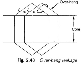
Over-hang leakage:
This is the Magnetic Leakage Flux in Induction Motor which surrounds the end conductors of the winding (stator/ rotor) as shown in Fig. 5.48. Its path mainly lies through air but a part of it may be located in the core-iron or the iron of end shields. The amount of this leakage depends upon the proximity of conductors and their relative location with respect to both the core and end-shields. This leakage is generally small because of the large air paths involved. It is particularly insignificant in the squirrel-cage induction machine rotor which has no over-hang.
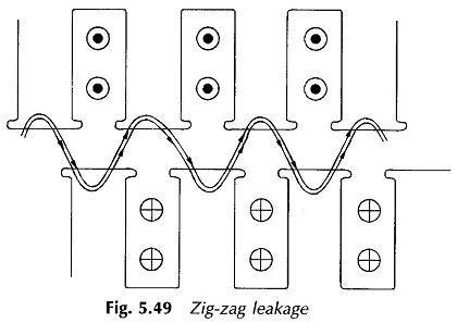
Zig-zag leakage:
In the case of induction machines both the stator and rotor are slotted so that some of the flux follows the path alternating between stator and rotor teeth as shown in Fig. 5.49. This flux therefore alternately links conductors in stator and rotor slots and is known as zig-zag leakage. Because of its nature it cannot be clearly assigned to either the stator or rotor windings. It is usually considered empirically that half of this flux links the stator winding while the other half links the rotor winding. This type of Magnetic Leakage Flux in Induction Motor is an exclusive feature of the induction machine and its value is a function of the percentage of the slot-pitch occupied by tooth in the rotor and stator and upon the length of the air-gap.
Harmonic leakage:
This kind of leakage results when the winding distribution on the stator and rotor are dissimilar. The main flux then has a harmonic component not corresponding to either winding and this excess flux has the effect of leakage flux. The detailed treatment of this kind of leakage is beyond the scope of this book.
Leakage reactance:
The leakage flux of various kinds as enumerated above, linking one of the windings, causes that winding to possess leakage reactance which can be considered as a lumped parameter in series in the circuit model of the machine whose effect is to cause a voltage drop in the machine. Since the field windings of dc and synchronous machines carry direct current, the Magnetic Flux Leakage linking them in no way affects the machine steady-state performance.