Gunn Diode Working Principle:
A practical Gunn Diode Working Principle consists of a slice like the one shown in Figure 12-24, sometimes with a buffer layer between the active layer and the substrate, mounted in any of a number of packages, depending on the manufacturer, the frequency and the power level. Encapsulation identical to that shown for varactor diodes in common. The power that must be dissipated is quite comparable.
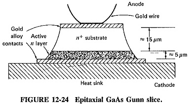
Gunn Diode Working Principle are grown epitaxially out of GaAs or InP doped with silicon, tellurium or selenium. The substrate, used here as an ohmic contact, is highly doped for good conductivity, while the thin active layer is less heavily doped. The gold alloy contacts are electrodeposited and used for good ohmic contact and heat transfer for subsequent dissipation. Diodes have been made with active layers varying in thickness from 40 to about 1 μm at the highest frequencies. The actual structure is normally square, and so far GaAs diodes predominate commercially.
Gunn Diode Performance:
As a good approximation, the equivalent circuit of a GaAs X-band Gunn Diode Working Principle consists of a negative resistance of about 100 ohms (100 Ω) in parallel with a capacitance of about 0.6 pF. Such a commercial diode will require a 9-V dc bias, and, with an operating current of 950 mA, the dissipation in its (cathode) heat sink will be 8.55 W. Given that the output (anywhere in the range 8 to 12.4 GHz) is 300 mW, the efficiency is seen to be 3.5 percent. A higher-frequency Gunn diode, operating over the range of 26.5 to 40 GHz, might produce an output of 250 mW with an efficiency of 2.5 percent.
Overall, GaAs Gunn diodes are available commercially for frequencies from 4 GHz (1 to 2 W CW maximum) to about 100 GHz (50 mW CW maximum). Over that range, the maximum claimed efficiencies drop from 20 to about 1 percent, but for most commercial diodes 2.5 to 5 percent is normal. InP diodes, not yet as advanced commercially, have a performance that ranges from 500 mW CW at 45 GHz (efficiency of 6 percent) to 100 mW CW at 90 GHz (efficiency of 4.5 percent); higher powers and operating frequencies are expected. Other options available include two or more diodes in one oscillator package for higher CW outputs, and diodes for pulsed outputs. In the latter case, commercial diodes produce up to a few dozen watts pulsed, with 1 percent duty cycles and efficiencies somewhat better than for CW diodes.
Gunn Oscillators:
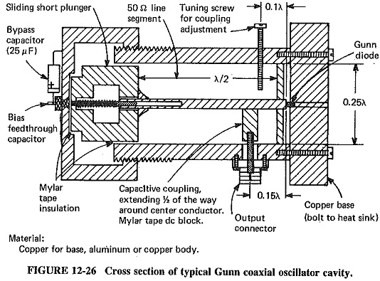
Since the Gunn Diode Working Principle consists basically of a negative resistance, all that is required in principle to make it into an oscillator is an inductance to tune out the capacitance, and a shunt load resistance not greater than the negative resistance. This has already been discussed in conjunction with the tunnel diode. In practice, a coaxial cavity operating in the TEM mode has been found the most convenient for fixed frequency (but with some mechanical tuning) operation. A typical coaxial Gunn oscillator is shown in Figure 12-26. If some electrical tuning is required as well, a varactor may be placed in the cavity, at the opposite end to the Gunn diode. The dimensions shown in Figure 12-26 are selected to provide suitable diode mounting and dissipation, as well as freedom from spurious mode oscillations.
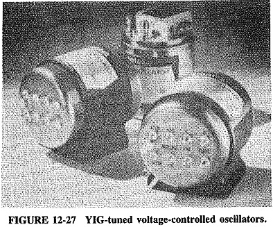
YIG-tuned Gunn VCOs are available for instrument applications, featuring frequency ranges as large as 2 octaves, much greater than is possible with varactors. A selection of such oscillators is shown in Figure 12-27. The 300-g, 50 X 50 mm package contains a Gunn slice on a heat sink, and a cavity with a small YIG sphere. There is a heater for the YIG sphere, to keep it at a constant temperature, and a coil for altering the magnetic field. The instantaneous frequency of oscillation is governed by the cavity frequency, which in turn depends on the YIG sphere and the magnetic field by which it is surrounded. It is the Gunn diode, rather than the tuning mechanism, that determines the frequency limits. When the frequency of the resonator is changed, the diode itself responds by generating its domain at a distance from the anode such that the transit time of the domain corresponds to a cycle of oscillations. As frequency is raised, the formation point of the domain moves closer to the anode. The oscillations eventually stop when this point is more than halfway across the slice. Avantek oscillators of the type shown in Figure 12-27 cover the range from 1 to 12.4 GHz, with typically octave tuning (or sweeping) ranges for each. Frequency modulation is also possible, via the terminals provided, and in all very rapid frequency changes can be made. Such VCOs are designed as backward-wave oscillator replacements, certainly at the lower end of the BWO’s operating spectrum. Typical power outputs range up to 50 mW, and total power consumption may be 5 W, including power for the YIG sphere.
Finally, it should be mentioned that the noise performance of Gunn oscillators is quite acceptable. Spurious AM noise is on par with that of the klystron (which itself is very good), while spurious FM noise is worse, but not too high for normal applications. Injection locking with a low-amplitude, high-stability signal helps to reduce FM noise quite significantly.
Gunn Diode Amplifiers:
As was shown in connection with the tunnel diode, a device exhibiting negative resistance may be used as an amplifier, and of course the Gunn diode qualifies in this respect. However, Gunn diode amplifiers are not used nearly as much as Gunn oscillators. The reasons are many. On the one hand, Gunn diode amplifiers cannot compete for power output and low noise with GaAs FET amplifiers at frequencies below about 30 GHz, and at higher frequencies they cannot compete with the power output or efficiency of electron tube or IMPATT (see next section) amplifiers. Accordingly, the niche which is left for them is as low- to medium-power medium-noise amplifiers in the 30- to 100-GHz frequency range. Over that range, they are capable of amplifying with noise figures of the order of 20 to 30 dB, relatively low efficiency and power gain per stage, and an output power that is perhaps two to four times as high would be expected from a single-diode oscillator (this is achieved by combining the output of several diodes in the final stage). One avenue of approach for improvement is to use a hybrid tunnel diode-Gunn diode amplifier, in which the tunnel diode input stages significantly reduce the noise figure. Noting that the foregoing applies to gallium arsenide diodes, another avenue of approach is to use indium phosphide devices. The early results with InP Gunn Diode Working Principle are most encouraging, with noise figures as low as 12 dB reported for amplifiers in the 50- to 60-GHz range.
For reasons identical to those applying to YIG-tuned Gunn oscillators, Gunn amplifiers, be they GaAs or InP, are capable of broad-band operation, 2:1 bandwidth ranges being not unusual. They are greatly superior to IMPATT amplifiers in this respect.
Application of Gunn Diode:
Gunn diode applications Having taken the microwave world more or less by storm, Gunn diode oscillators are widely used and also intensely researched and developed. They are employed frequently as low- and medium-power oscillators in microwave receivers and instruments. The majority of parametric amplifiers now use Gunn diodes as pump sources. They have the advantage over IMPATT diodes of having much lower noise, this being an important criterion in the selection of a pump oscillator. Where very high pump frequencies are required, the technique of using a lower-frequency Gunn oscillator and doubling the frequency with a varactor multiplier is often used.
The higher-power Gunn oscillators (250 to 2000 mW) are used as power output oscillators, generally frequency-modulated, in a wide variety of low-power transmitter applications. These currently include police radar, CW Doppler radar, burglar alarms and aircraft rate-of-climb indicators.