What is a Filter Circuit?:
A network designed to attenuate certain frequencies but pass others without attenuation is called a filter. A filter circuit thus possesses at least one pass band, which is a band of frequencies in which the output is approximately equal to the input (attenuation is zero) and an attenuation band in which output is zero (attenuation is infinite). The frequencies that separate the various pass and attenuation bands are called the cutoff frequencies.
An important characteristics of all filter networks is that they are constructed from purely reactive elements.
In measurement systems, the transducer often does not measure the physical parameter (measurand) precisely. The information present is not in standard form, hence the need for further filtering and analysis. The main factors that must be considered for accuracy are signal to noise (S/N) ratio, response time and bandwidth over which the measurements are desired. Among these the S/N ratio is the most important parameter that needs to be considered, and the use of a signal filter becomes a necessity when low level or high resolution measurements are required. The signal originating from a transducer is fed to the signal conditioner. The output signal obtained from a transducer must be reproduced faithfully. In order to obtain a faithful reproduction of the signal, it becomes necessary to eliminate any spurious or unwanted signals which may get introduced into the system, either at the transduction stage or at the signal conditioning stage.
The filter are thus designed to pass signals of desired frequencies and reject signals of unwanted frequencies (harmonics and noise).
Fundamental Theorem of Filter Circuit:
Assuming the filter is correctly terminated in its characteristic impedance Zo, the following is applicable.
“Over the range of frequencies for which the characteristic impedance Zo of a filter is purely resistive (real), the attenuation (α) will be zero.”
“Over the range of frequencies for which the characteristic impedance Zo is purely reactive (imaginary), the attenuation (α) will be greater than zero.”
Mathematical Proof of the Theorem:
The fundamental theorem on filters can be proved by considering a simple filter circuit in the form of a symmetrical T network. Let the T network consist of series and shunt elements, as shown in Fig. 15.1(a).
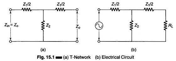
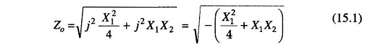
The characteristic impedance Zo of the network in Fig. 15.1 is given by

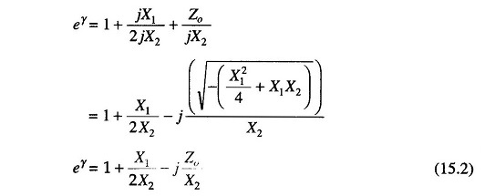
Similarly, the current ratio or the propagation constant

Being a filter network, both Z1 and Z2 are reactive elements. Let Z1 = jX1 and Z2 = jX2.
There will be two cases for impedance values of Zo, depending on the value and sign of X1 and X2.
Hence
Similarly
Case 1:
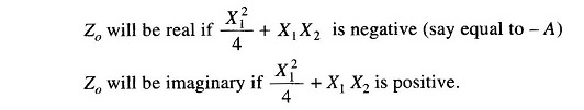
When Zo is real
Let

Then from Eq. (15.1) we get
![]()
Also from Eq. (15.2) we have
Since
![]()
but
![]()
where
- α = attenuation constant
- β = phase shift constant
Considering attenuation only
![]()
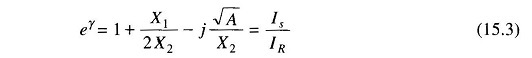
Therefore, From Eq.(15.3)
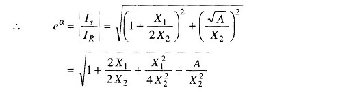
But as
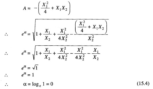
From Eq. (15.4) we see that attenuation is zero, if Zo is real.
Case 2:
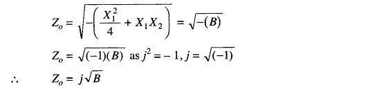
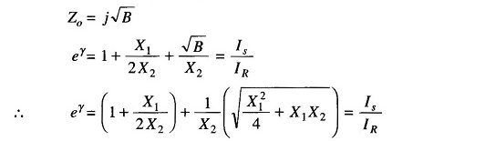
When Zo is imaginary [purely reactive]
For Zo to be imaginary X21/4+X1X2 should be positive.
Therefore, Let

from Eq. (15.1) we get
Similarly the value of eγ from Eq. (15.2) will be

as
Taking the modulus
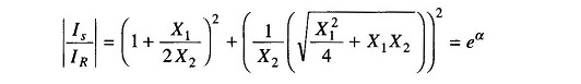
Since
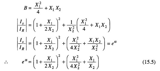
Hence α is greater than one and real. Therefore if Zo is imaginary, α cannot be zero, and the filter circuit will have an attenuation band.