Television System Articles:
Introduction to Television: Introduction to Television tells first thing of seeing at a distance. To be successful, a television system may be required to reproduce faithfully: The shape of each object, or structural content The relative brightness of each object, or tonal content Motion, … (Read More)
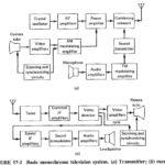
Television Systems and Standards: It is clear that a large amount of information must be broadcast by a television transmitter and that there are a variety of ways in which this can be done. Accordingly, a need exists for Television Systems … (Read More)
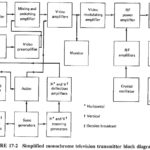
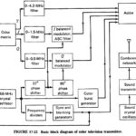
Monochrome Television Transmitter: As shown in the block diagram of Figure 17-2, a Monochrome Television Transmitter system is quite unlike any of the transmission systems studied previously. This section will deal with the fundamental, “straightforward” blocks, while the functions specific to … (Read More)
Sawtooth Waveform in Beam Scanning: As previously discussed, one complete frame of a TV picture is scanned 30 times per second, in a manner very similar to reading this page. As our eyes are told where to look by our brain, … (Read More)
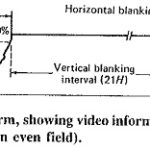
TV Video Waveform: Blanking – TV Video Waveform voltage is limited to certain amplitude limits. Thus, for example, the white level corresponds to 12.5 percent (±2.5 percent) modulation of the carrier, and the black level corresponds to approximately 67.5 percent modulation. … (Read More)
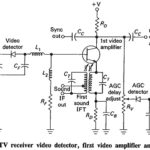
Monochrome Television Receiver Block Diagram: Monochrome Television Receiver Block Diagram as shown in Figure 17-9, TV receivers use the superheterodyne principle. There is extensive pulse circuitry, to ensure that the demodulated video is displayed correctly. To that extent the TV receiver … (Read More)
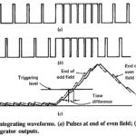
TV Receiver Synchronizing Circuits: The task of the TV Receiver Synchronizing Circuits is to process received information, in such a way as to ensure that the vertical and horizontal oscillators in the receiver work at the correct frequencies. This task is broken … (Read More)
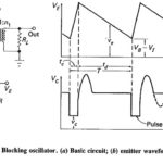
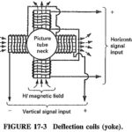
Vertical Deflection Circuit in TV: The Vertical Deflection Circuit in TV include the vertical oscillator and amplifier for vertical scanning at 60 Hz and a similar horizontal arrangement for scanning at 15,750 Hz. For either scanning, the oscillator provides a deflection … (Read More)
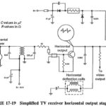
Television Horizontal Deflection Circuit: The function performed by these circuits is exactly the same as already described for the vertical deflection circuits. There are some practical differences. The major one is the much higher horizontal frequency. This makes a lot of … (Read More)
Color TV Transmission and Reception: If color TV had come before monochrome TV, the system would be far simpler than it actually is now. Since only the three additive primary colors (red, blue and green) need be indicated for all colors … (Read More)
Color TV Transmission: Having discussed the manner of indicating luminance and the two components of chrominance in Color TV Transmission, it is now necessary to investigate how they may be, modulated and sent in the 6-MHz channel, without interference to monochrome … (Read More)
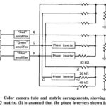
Color Picture Tube Working: A Color Picture Tube Working requires correct sweep currents, input voltages and drive voltages. Having said this very quickly, it is now a good idea to examine the circuit block of Figure 17-23, to gauge the complexity … (Read More)
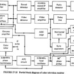
Color Television Receiver Block Diagram: Figure 17-25 shows the block diagram of a Color Television Receiver Block Diagram, but for simplicity the circuits shown in Figure 17-23 are omitted. Interconnection points are shown on both diagrams, so that there should be … (Read More)