Diode Applications Articles:
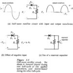
Half Wave Rectifier Circuit: A basic diode Half Wave Rectifier Circuit is shown in Fig. 3-1(a). An alternating input voltage is applied to a single diode connected in series with a load resistor RL. The diode is forward biased during the … (Read More)
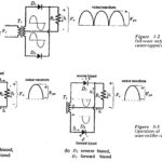
Two Diode Full Wave Rectifier Circuit: The Fig. 3-2 shows the Two Diode Full Wave Rectifier Circuit, and its input voltage is supplied from a transformer (T1) with a center-tapped secondary winding. The circuit is essentially a combination of two half-wave … (Read More)
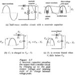
Half Wave Rectifier with Capacitor Filter: Half Wave Rectifier with Capacitor Filter – When a sinusoidal alternating voltage is rectified, the resultant waveform is a series of positive (or negative) half-cycles of the input waveform; it is not direct voltage. To … (Read More)
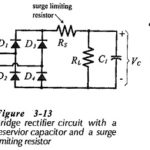
Full Wave Rectifier DC Power Supply: Like half-wave rectifiers, full-wave rectifiers require filter circuits to convert the output waveform to direct voltage. Figure 3-13 shows a Full Wave Rectifier DC Power Supply with a reservior capacitor and a surge limiting resistor. … (Read More)
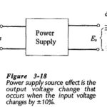
Power Supply Source Effect in Semiconductor: Power Supply Source Effect in Semiconductor shows that the ac supply to the input of a transformer in a dc power supply does not always remain constant. A ±10% variation in the ac source voltage … (Read More)
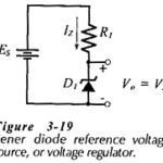
Zener Diode Voltage Regulator Circuit: Regulator Circuit With No Load – The most important application of Zener Diode Voltage Regulator Circuit is dc voltage regulator circuits. These can be the simple regulator circuit shown in Fig. 3-19, or the more complex … (Read More)
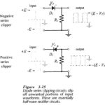
Diode Series Clipper Circuit: The function of a Diode Series Clipper Circuit (or limiter) is to clip off an unwanted portion of a waveform. This is sometimes necessary to protect a device or circuit that might be destroyed by a large … (Read More)
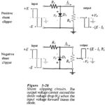
Shunt Clipping Circuits: A positive Shunt Clipping Circuits is illustrated in Fig. 3-28(a). Here the diode is connected in shunt (or parallel) with the output terminals. When the input is negative, the diode is reverse biased and only a small voltage … (Read More)
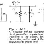
Clamping Circuit: Negative and Positive Voltage Clamping Circuits – A clamping circuit, also known as a dc restorer, changes the dc voltage level of a waveform, but does not affect its shape Consider the clamping circuit shown in Fig. 3-33. When the … (Read More)
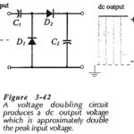
Voltage Doubler Circuit: A Voltage Doubler Circuit produces an output voltage which is approximately double the peak voltage of the input waveform. Consideration of the voltage doubler circuit diagram in Fig. 3-42 shows that it is simply a combination of two … (Read More)
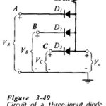
Diode Logic Circuits: A Diode Logic Circuits produces an output voltage which is either high or low, depending upon the levels of several input voltages. The two basic logic circuits are the AND gate and the OR gate. Diode AND Gate: Figure 3-49 … (Read More)