Equivalent Circuit of Single Phase Induction Motor:
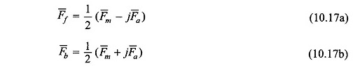
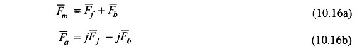
Equivalent Circuit of Single Phase Induction Motor – The winding unbalance and the fact that both the main and auxiliary windings are fed by the same supply result in unbalanced main and auxiliary fields. The phasor along the winding axes can be split into symmetrical components F̅f and F̅b as given by Eqs (10.17a) and (10.17b). The forward component set F̅f and jF̅f produces a forward rotating field; similarly the backward component set F̅b and -jF̅b results in a backward rotating field.
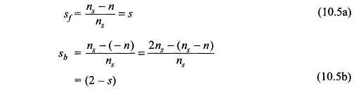
The rotor slips with respect to the two rotating fields are s and (2 – s) respectively as given by Eqs (10.5a) and (10.5b) and as a result the magnetizing and rotor circuits as seen by the two rotating fields with reference to the main winding are different and are shown in Figs 10.22(a) and 10.22(b).
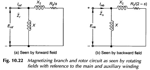
It is noted that no-load losses have been neglected and therefore the core-loss conductance has not been shown in both the circuits. The impedance seen by Emf, the forward field induced emf of the main winding, is
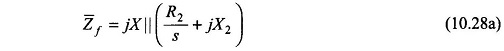
and the impedance seen by the Emb, backward field induced emf in the main winding, is
![]()
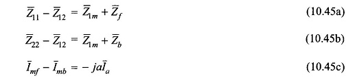
Hence
![]()
and
![]()
where
- I̅mf = forward component current in main winding
- I̅mb = backward component current in main winding
Of course
![]()
Equations (10.16a) and (10.16b) will now be converted into current form.
Let
Nm = equivalent number of main windings turns
Na = equivalent number of auxiliary winding turns
Define
![]()
Then from Eqs (10.16a) and (10.16b)
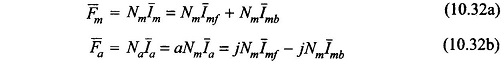
From Eqs (10.32a) and (10.32b)
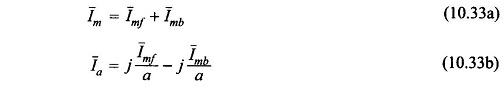
The current in the auxiliary winding is I̅a but since the turns of auxiliary and main winding are different , the auxiliary winding current as seen from the main winding is equal to
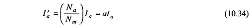
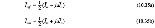
From Eqs (10.33a) and (10.33b) the symmetrical components of mail and auxiliary winding currents with reference to the min winding can be expressed as
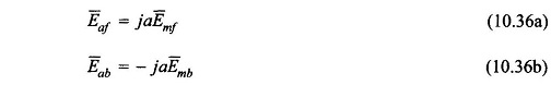
The forward field reaches the auxiliary winding 90° elect. ahead of the main winding and vice versa for the backward rotating field. Thus the emf’s in the auxiliary winding induced by the two fields are:
Also let the main and auxiliary winding terminal voltages be V̅m and V̅a respectively. The auxiliary winding voltage is equal to (Va/a) as seen from the main winding. This set of voltages can also be split into symmetrical components as
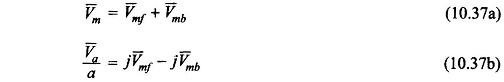
or alternatively
Now consider the main winding terminal voltage V̅m. It comprises three components: the emf induced by the forward rotating field, the emf induced by backward rotating field and the voltage drop in the winding impedance Z̅1m owing to current Im flowing through it. Thus
![]()
Substituting for E̅mf and E̅mb from Eqs (10.29a) and (10.29b)
![]()
which is represented by the Equivalent Circuit of Single Phase Induction Motor of Fig. 10.23(a).
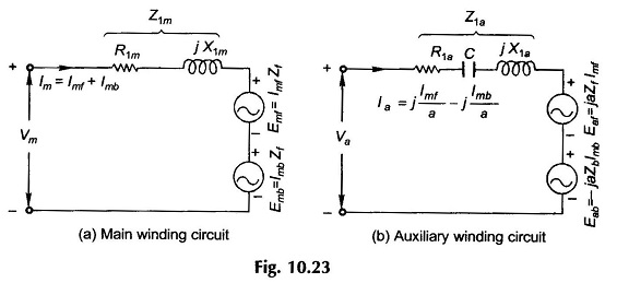
Similarly the auxiliary winding terminal voltage V̅a comprises three components,
i.e.
![]()
where Z̅1a is the winding impedance of the auxiliary winding which in general has a capacitor included in it (starting/running capacitor). Using Eqs (10.36a) and (10.36b),
whose Equivalent Circuit of Single Phase Induction Motor representation is given in Fig. (10.23b).
Substituting Im from Eq. (10.33a) in Eq. (10.39b),
![]()
Similarly substituting Ia from Eq. (10.33b) in Eq. (10.40c),
With V̅m and V̅a as expressed in Eqs (10.41a) and (10.41b), one obtains from Eqs (10.38a) and (10.38b)
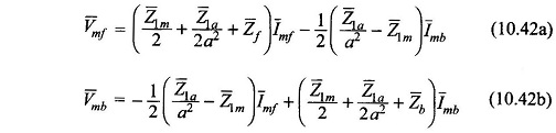
Defining
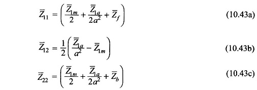
Equations (10.42a) and (10.42b) can be written as
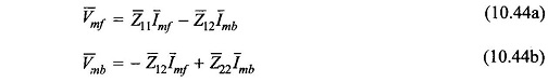
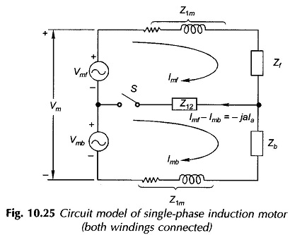
Equations (10.44a), (10.44b) and (10.37a) are represented by the Equivalent Circuit of Single Phase Induction Motor of Fig. 10.24.
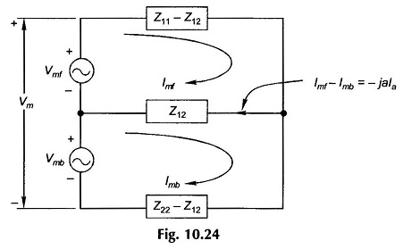
It is further noted that
From these the Equivalent Circuit of Single Phase Induction Motor of Fig. 10.24 can be drawn in the form of Fig.10.25. In Fig. 10.25 disconnecting the auxiliary winding under running condition is equivalently represented as the opening of switch S.
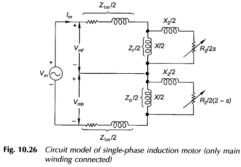
Once the auxiliary Winding is disconnected.
By doubling the current and reducing the impedance to half the circuit model of Fig. 10.26 is obtained. It may be seen that this is the same circuit model as already presented in Fig. 10.5(c) on a heuristic basis.
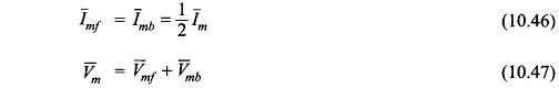
From Eqs. (10.42a) and (10.42b),
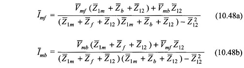
The winding currents are then given by
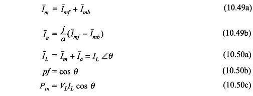
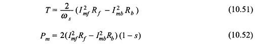
The developed torque and mechanical power are given by
Capacitor Impedance for Balanced Operation at Specific Speed:
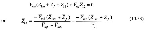
For balanced single-phase operation

or from Eq. (10.48b)
From Eq. (10.38b)

For single-phase operation
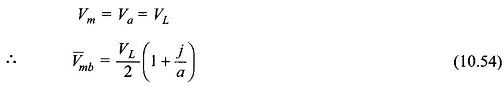
Substituting Eq. (10.54) in Eq. (10.53)
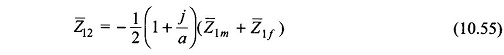
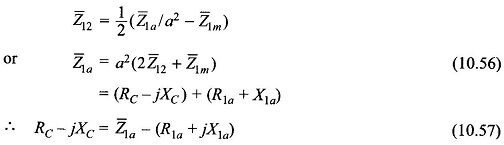
With Z̅12 defined in Eq. (10.43b)