Cavity Magnetron Working:
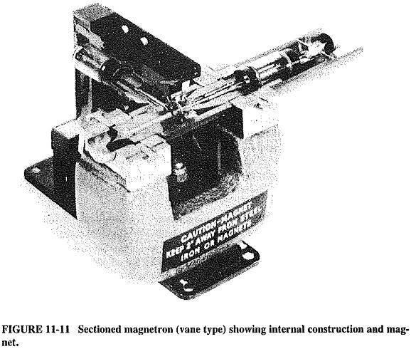
The Cavity Magnetron Working, which will be referred to as the magnetron, is a diode, usually of cylindrical construction. It employs a radial electric field, an axial magnetic field and an anode structure with permanent cavities. As shown in Figure 11-10, the cylindrical cathode is surrounded by the anode with cavities, and thus a radial dc electric field will exist. The magnetic field, because of a magnet like the one in Figure 11-11, is axial, i.e., has lines of magnetic force passing through the cathode and the surrounding interaction space. The lines are thus at right angles to the structure cross section of Figure 11-10. The magnetic field is also dc, and since it is perpendicular to the plane of the radial electric field, the magnetron is called a crossed-field device.
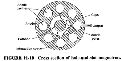
The output is taken from one of the cavities, by means of a coaxial line as indicated in both Figures 11-10 and 11-11, or through a waveguide, depending on the power and frequency. With regard to Figure 11-11, note that the anode surround has been removed to make the inside visible. Note also that the Cavity Magnetron Working is of a somewhat different type, being identical to the resonator. The output coupling loop leads to a cavity resonator to which a waveguide is connected, and the overall output from this magnetron is via waveguide. The rings interconnecting the anode poles are used for strapping, and the reason for their presence will be explained. Finally, the anode is normally made of copper, regardless of its actual shape.
The magnetron has a number of resonant cavities and must therefore have a number of resonant frequencies and/or modes of oscillation. Whatever mode is used, it must be self-consistent. For example, it is not possible for the eight-cavity magnetron (which is often used in practice) to employ a mode in which the phase difference between the adjacent anode pieces is 30°. If this were done, the total phase shift around the anode would be 8 x 30° = 240°, which means that the first pole piece would be 120° out of phase with itself! Simple investigation shows that the smallest practical phase difference that can exist here between adjoining anode poles is 45°, or π/4 rad, giving a self-consistent overall phase shift of 360° or 2π rad. This π/4 mode is seldom used in practice because it does not yield suitable characteristics, and the π mode is preferred for rather complex reasons. In this mode of operation, the phase difference between adjacent anode poles is π rad or 180°.
Effects of Magnetic Field:
Since any electrons emitted by the magnetron cathode will be under the influence of the de magnetic field, as well as an electric field, the behavior of electrons in a magnetic field must first be investigated. There, electrons were in the crystalline structure of a magnetic material, whereas here they are moving in the vacuum of the anode interaction space.
A moving electron represents a current, and therefore a magnetic field exerts a force upon it, just as it exerts a force on a wire carrying a current. The force thus exerted has a magnitude proportional to the product Bev, where e and v are the charge and velocity of the electron, respectively, and B is the component of the magnetic field in a plane perpendicular to the direction of travel of the electron. This force exerted on the electron is perpendicular to the other two directions. If the electron is moving forward horizontally, and the magnetic field acts vertically downward, the path of the electron will be curved to the left. Since the magnetic field in the magnetron is constant, the force of the magnetic field on the electron (and therefore the radius of curvature) will depend solely on the forward (radial) velocity of the electron.
Effect of magnetic and electric fields:
When magnetic and electric fields act simultaneously upon the electron, its path can have any of a number of shapes dictated by the relative strengths of the mutually perpendicular electric and magnetic fields. Some of these electron paths are shown in Figure 11-12 in the absence of oscillations in a magnetron, in which the electric field is constant and radial, and the axial magnetic field can have any number of values.
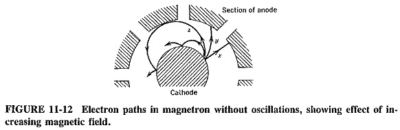
When the magnetic field is zero, the electron goes straight from the cathode to the anode, accelerating all the time under the force of the radial electric field. This is indicated by path x in Figure 11-12. When the magnetic field has a small but definite strength, it will exert a lateral force on the electron, bending its path to the left (here). Note, as shown by path y of Figure 11-12, that the electron’s motion is no longer rectilinear. As the electron approaches the anode, its velocity continues to increase radially as it is accelerating. The effect of the magnetic field upon it increases also, so that the path curvature becomes sharper as the electron approaches the anode.
It is possible to make the magnetic field so strong that electrons will not reach the anode at all. The magnetic field required to return electrons to the cathode after they have just grazed the anode is called the cutoff field. The resulting path is z in Figure 11-12. Knowing the value of the required magnetic field strength is important because this cutoff field just reduces the anode current to zero in the absence of oscillations. If’the magnetic field is stronger still, the electron paths as shown will be more curved still, and the electrons will return to the cathode even sooner (only to be reemitted). All these paths are naturally changed by the presence of any RF field due to oscillations, but the state of affairs without the RF field must still be appreciated, for two reasons. First, it leads to the understanding of the oscillating magnetron. Second, it draws attention to the fact that unless a magnetron is oscillating, all the electrons will be returned to the cathode, which will overheat and ruin the tube. This happens be-cause in practice’ the applied magnetic field is greatly in excess of the cutoff field.
Operation:
Once again it will be assumed that oscillations are capable of starting in a device having high-Q cavity resonators, and the mechanism whereby these oscillations are maintained will be explained.
π-mode oscillations:
As explained in the preceding section, self-consistent oscillations can exist only if the phase difference between adjoining anode poles is nπ/4, where n is an integer. For best results, n = 4 is used in practice. The resulting err-mode oscillations are shown in Figure 11-13 at an instant of time when the RF voltage on the top left-hand anode pole is maximum positive. It must be realized that these are oscillations. A time will thus come, later in the cycle, when this pole is instantaneously maximum negative, while at another instant the RF voltage between that pole and the next will be zero.
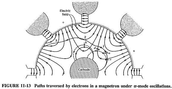
In the absence of the RF electric field, electrons a and b would have followed the paths shown by the dotted lines a and b, respectively, but the RF field naturally modifies these paths. This RF field, incidentally, exists inside the individual resonators also, but it is omitted here for simplicity. The important fact is that each Cavity Magnetron Working acts in the same way as a short-circuited quarter-wave transmission line. Each gap corresponds to a maximum voltage point in the resulting standing-wave pattern, with the electric field extending into the anode interaction space, as shown in Figure 11-13.
Effect of combined fields on electrons:
The presence of oscillations in the magnetron brings in a tangential (RF) component of electric field. When electron a is situated (at this instant of time) at point 1, the tangential component of the RF electric field opposes the tangential velocity of the electron. The electron is retarded by the field and gives energy to it (as happened in the reflex klystron). Electron b is so placed as to extract an equal amount of energy from the RF field, by virtue of being accelerated by it. For oscillations to be maintained, more energy must be given to the electric field than is taken from it. Yet, on the face of it, this is unlikely to be the case here because there are just as many electrons of type a as of type b. Note that electron a spends much more time in the RF field than electron b. The former is retarded, and therefore the force of the dc magnetic field on it is diminished; as a result, it can now move closer to the anode. If conditions are arranged so that by the time electron a arrives at point 2 the field has reversed polarity, this electron will once again be in a position to give energy to the RF field (though being retarded by it). The magnetic force on electron a diminishes once more, and another interaction of this type occurs (this time at point 3). This assumes that at all times the electric field has reversed polarity each time this electron arrives at a suitable interaction position. In this manner, “favored” electrons spend a considerable time in the interaction space and are capable of orbiting the cathode several times before eventually arriving at the anode.
However, an electron of type b undergoes a totally different experience. It is immediately accelerated by the RF field, and therefore the force exerted on it by the dc magnetic field increases. This electron thus returns to the cathode even sooner than it would have in the absence of the RF field. It consequently spends a much shorter time in the interaction space than the other electron. Hence, although its interaction with the RF field takes as much energy from it as was supplied by electron a, there are far fewer interactions of the b type because such electrons are always returned to the cathode after one, or possibly two, interactions. On the other hand, type a electrons give up energy repeatedly. It therefore appears that more energy is given to the RF oscillations than is taken from them, so that oscillations in the magnetron are sustained. The only real effect of the “unfavorable” electrons is that they return to the cathode and tend to heat it, thus giving it a dissipation of the order of 5 percent of the anode dissipation. This is known as back-heating and is not actually a total loss, because it is often possible in a magnetron to shut off the filament supply after a few minutes and just rely on the back-heating to maintain the correct cathode temperature.
Bunching:
It may be shown that the Cavity Magnetron Working, like the klystrons, causes electrons to bunch, but here this is known as the phase focusing effect. This effect is rather important. Without it, favored electrons would fall behind the phase change of the electric field across the gaps, since such electrons are retarded at each interaction with the RF field. To see how this effect operates, it is most convenient to consider another electron, such as c of Figure 11-13
Electron c contributes some energy to the RF field. However, it does not give up as much as electron a, because the tangential component of the field is not as strong at this point. As a result, this electron appears to be somewhat less useful than electron a, but this is so only at first. Electron c encounters not only a diminished tangential RF field but also a component of the radial RF field, as shown. This has the effect of accelerating the electron radially outward. As soon as this happens, the dc magnetic field exerts a stronger force on electron c, tending to bend it back to the cathode but also accelerating it somewhat in a counterclockwise direction. This, in turn, gives this electron a very good chance of catching up with electron a. In a similar manner, electron d (shown in Figure 11-13) will be retarded tangentially by the dc magnetic field. It will therefore be caught up by the favored electron; thus, a bunch takes shape. In fact, it is seen that being in the favored position means (to the electron) being in a position of equilibrium. If an electron slips back or forward, it will quickly be returned to the correct position with respect to the RF field, by the phase-focusing effect just described.
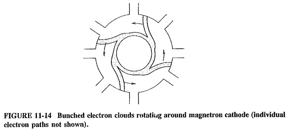
Figure 11-14 shows the wheel-spoke bunches in the Cavity Magnetron Working. These bunches rotate counterclockwise with the correct velocity to keep up with RF phase changes between adjoining anode poles. In this way a continued interchange of energy takes place, with the RF field receiving much more than it gives. The RF field changes polarity. Each favored electron, by the time it arrives opposite the next gap, meets the same situation of there being a positive anode pole above it and to the left, and a negative anode pole above it and to the right. It is not difficult to imagine that the electric field itself is rotating counterclockwise at the same speed as the electron bunches. The cavity magnetron is called the traveling-wave magnetron precisely because of these rotating fields.
Practical Considerations:
The operating principles of a device are important but do not give the entire picture of that particular device. A number of other significant aspects of magnetron operation will now be considered.
Strapping:
Because the magnetron has eight (or more) coupled cavity resonators, several different modes of oscillation are possible. The oscillating frequencies corresponding to the different modes are not the same. Some are quite close to one another, so that, through mode jumping, a 3-cm π-mode oscillation which is normal for a particular magnetron could, spuriously, become a 3.05-cm 3/4 π-mode oscillation. The dc electric and magnetic fields, adjusted to be correct for the IT mode, would still support the spurious mode to a certain extent, since its frequency is not too far distant. The result might well be oscillations of reduced power, at the wrong frequency.
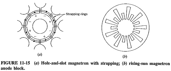
Magnetrons using identical cavities in the anode block normally employ strap-ping to prevent mode jumping. Such strapping was shown in Figure 11-11 for the vane cavity system, and it is now seen in Figure 11-15a for the hole-and-slot Cavity Magnetron Working arrangement. Strapping consists of two rings of heavy-gauge wire connecting alternate anode poles. These are the poles that should be in phase with each other for the π mode. The reason for the effectiveness of strapping in preventing mode jumping may be simplified by pointing out that, since the phase difference between alternate anode poles is other than 2π rad in other modes, these modes will quite obviously be prevented. The actual situation is somewhat more complex.
Strapping may become unsatisfactory because of losses in the straps in very high-power magnetrons or because of strapping difficulties at very high frequencies. In the latter case, the cavities are small, and there are generally a lot of them (16 and 32 are common numbers), to ensure that a suitable RF field is maintained in the interaction space. This being so, so many modes are possible that even strapping may not prevent mode jumping. A very good cure consists in having an anode block with a pair of Cavity Magnetron Working systems of quite dissimilar shape and resonant frequency. Such a rising-sun anode structure is shown in Figure 11-15b and has the effect of isolating the 7π-mode frequency from the others. Consequently the magnetron is now unlikely to oscillate at any of the other modes, because the dc fields would not support them. Note that strapping is not required with the rising-sun magnetron.
Frequency Pulling and Pushing in Magnetron:
It should be recognized that the resonant frequency of magnetrons can be altered somewhat by changing the anode voltage. Such frequency pushing is due to the fact that the change in anode voltage has the effect of altering the orbital velocity of the electron clouds of Figure 11-14. This in turn alters the rate at which energy is given up to the anode resonators and therefore changes the oscillating frequency, cavity bandwidth permitting. The effect of all this is that power changes will result from inadvertent changes of anode voltage, but voltage tuning of magnetrons is quite feasible.
Like any other oscillator, the magnetron is susceptible to frequency variations due to changes of load impedance. This will happen regardless of whether such load variations are purely resistive or involve load reactance variations, but it is naturally more severe for the latter. The frequency variations, known as frequency pulling, are caused by changes in the load impedance reflected into the cavity resonators. They must be prevented, all the more so because the magnetron is a power oscillator. Unlike most other oscillators, it is not followed by a buffer.
The various characteristics of a magnetron, including the optimum combinations of anode voltage and magnetic flux, are normally plotted on performance charts and Rieke diagrams. From these the best operating conditions are selected.