Cavity Resonators:
A cavity resonators is a piece of waveguide closed off at both ends with metallic planes. Where propagation in the longitudinal direction took place in the waveguide, standing waves exist in the resonator, and oscillations can take place if the resonator is suitably excited. Various aspects of cavity resonators will now be considered.
Waveguides are used at the highest frequencies to transmit power and signals. Similarly, cavity resonators are employed as tuned circuits at such frequencies. Their operation follows directly from that of waveguides.
Operation:
Until now, waveguides have been considered from the point of view of standing waves between the side walls and traveling waves in the longitudinal direction. If conducting end walls are placed in the waveguide, then standing waves, or oscillations, will take place if a source is located between the walls. This assumes that the distance between the end walls is nλp/2, where n is any integer. The situation is illustrated in Figure 10-35.
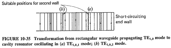
As shown here and discussed in a slightly different context of placement of the first wall ensures standing waves, and placement of the second wall permits oscillations, provided that the second wall is placed so that the pattern due to the first wall is left undisturbed. Thus, if the second wall is λp/2 away from the first, as in Figure 10-36, oscillations between the two walls will take place. They will then continue until all the applied energy is dissipated, or indefinitely if energy is constantly supplied. This is identical to the behavior of an LC tuned circuit.
It is thus seen that any space enclosed by conducting walls must have one (or more) frequency at which the conditions just described are fulfilled. hi other words, any such enclosed space must have at least one resonant frequency. Indeed, the completely enclosed waveguide has become a cavity resonator with its own system of modes, and therefore resonant frequencies. The TE and TM mode-numbering system breaks down unless the cavity has a very simple shape, and it is preferable to speak of the resonant frequency rather than mode.
Each cavity resonator has an infinite number of resonant frequencies. This can be appreciated if we consider that with the resonator of Figure 10-35 oscillations would have been obtained at twice the frequency, because every distance would now be λp, instead of λp/2. Several other resonant frequency series will also be present, based on other modes of propagation, all permitting oscillations to take place within the cavity. Naturally such behavior is not really desired in a resonator, but it need not be especially harmful. The fact that the cavity can oscillate at several frequencies does not mean that it will. Such frequencies are not generated spontaneously; they must be fed in.
Types:
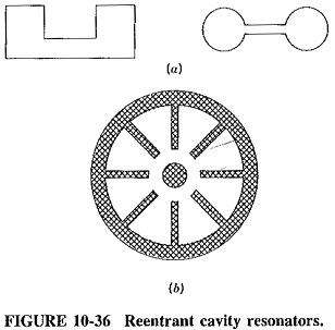
The simplest cavity resonators may be spheres, cylinders or rectangular prisms. However, such cavities are not often used, because they all share a common defect; their various resonant frequencies are harmonically related. This is a serious drawback in all those situations in which pulses of energy are fed to a cavity. The cavity is supposed to maintain sinusoidal oscillations through the flywheel effect, but because such pulses contain harmonics and the cavity is able to oscillate at the harmonic frequencies, the output is still in the form of pulses. As a result, most practical cavities have odd shapes to ensure that the various oscillating frequencies are not harmonically related, and therefore that harmonics are attenuated.
Some typical irregularly shaped resonators are illustrated. Those of Figure 10-36a might be used with reflex klystrons, whereas the resonator of Figure 10-36b is popular for use with magnetrons. They are known as reentrant resonators, that is, resonators so shaped that one of the walls reenters the resonator shape. The first two are figures of revolution about a central vertical axis, and the third one is cylindrical. Apart from being useful as tuned circuits, they are also given such shapes so that they can be integral parts of the above-named microwave devices, being therefore doubly useful. However, because of their shapes, they have resonant frequencies that are not at all easy to calculate.
Note that the general size of a cavity resonator, for a given dominant mode, is similar to the cross-sectional dimensions of a waveguide carrying a dominant mode of the same signal (this is merely an approximation, not a statement of equivalence). Note further that (as with quartz crystals) the lowest frequency of oscillations of a cavity resonator is also one of most intense oscillation, as a general rule.
Applications:
Cavity resonators are employed for much the same purposes as tuned LC circuits or resonant transmission lines, but naturally at much higher frequencies since they have the same overall frequency coverage as waveguides. They may be input or output tuned circuits of amplifiers, tuned circuits of oscillators, or resonant circuits used for filtering or in conjunction with mixers. In addition, they can be given shapes that make them integral parts of microwave amplifying and oscillating devices, so that almost all such devices use them.
One of the many applications of the cavity resonator is as a cavity wavemeter, used as a microwave frequency-measuring device. Basically it is a simple cavity of cylindrical shape, usually with a plunger whose insertion varies the resonant frequency. Adjustment is by means of a calibrated micrometer. The plunger has absorbent material on one side of it (the back) to prevent oscillations in the back cavity, and the micrometer is calibrated directly in terms of wavelength, from which frequency may be calculated.
A signal is fed to a cavity wavemeter through an input loop, and a detector is connected to it through an output loop. The size of the cavity is adjusted with the plunger until the detector indicates that pronounced oscillations are taking place, whereupon frequency or wavelength is read from the micrometer. Coaxial line wave-meters also exist, but they have a much lower Q than cavity wavemeters, perhaps 5000 as compared with 50,000.
Practical Considerations:
Having considered the more fundamental aspects of cavity resonators, we must now concentrate on two practical matters concerning them. Since tuned circuits cannot be used in practice unless it is possible to couple energy to or from them and are not of much practical use unless they are tunable, coupling and tuning must now be discussed.
Coupling to cavities:
Exactly the same methods may be used for coupling to cavity resonators as are employed with waveguides. Thus, various slots, loops and probes are used to good advantage when coupling of power into or out of a cavity is desired. It must be realized, however, that taking an output from a cavity not only loads it but also changes its resonant frequency slightly, just as in other tuned circuits. For a cavity, this can be explained by the fact that the insertion of a loop distorts the field that would otherwise have existed in the resonator. Hence a cavity may require retuning if such a loop is inserted or rotated to change the degree of coupling. It should also be mentioned that the one position of loop, probe or slot is quite capable of exciting several modes other than the desired one. This is unlikely to be a problem in practice, however, because the frequencies corresponding to these spurious modes are hardly likely to be present in the injected signal.
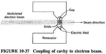
There is one form of coupling which is unlikely with waveguides, but quite common with cavity resonators, especially those used in conjunction with klystrons; this is coupling to an electron beam. The situation is illustrated in Figure 10-37, which shows a typical klystron cavity, together with the distribution of some of the electric field.
The beam passes through the center of the cavity. This is usually a figure of revolution about an axis coinciding with the center of the beam, with holes or mesh at its narrow gap to allow the passage of the beam. If the cavity is oscillating but the beam itself is unmodulated (having a uniform current density), then the presence of the electric field across the gap in the cavity will have an effect on the beam. This field will accelerate some electrons in it and retard others, depending on the size and polarity of the gap voltage at the time when electrons pass the gap. If the current of the beam is modulated and flows in pulses, as often happens in practice, the pulses will deliver energy to the cavity. This will cause oscillation if the pulse repetition rate corresponds to a resonant frequency of the cavity.
Tuning of cavities:
Precisely the same methods are used for tuning cavity resonators as were used for impedance matching of waveguides, with the adjustable screw, or post, perhaps the most popular. However, it is important to examine the effects of such tuning, and also loading, on the bandwidth and Q of the cavity resonator.
Q has the same meaning for cavity resonators as for any other tuned circuits and may be defined as the ratio of the resonant frequency to the bandwidth. However, it is perhaps more useful to base the definition of Q here on a more fundamental relation, i.e.,

Roughly speaking, energy is stored in the volume of the resonator and dissipated through its surface. Hence it follows that the shape giving the highest volume-to-surface-area ratio is likely to have the highest Q, all else being equal. Thus the sphere, cylinder and rectangular prism are used where high Q is the primary requirement. If a cavity is well designed and constructed, and plated on the inside with gold or silver, its unloaded Q will range from about 2000 for a reentrant cavity to 100,000 for a spherical one. Values somewhat in excess of 40,000 are also attainable for the spherical cavity when it is loaded.
When a cavity is tuned by means of a screw or sliding piston, its Q will suffer, and this should be taken into account. The Q decreases because of the extra area due to the presence of the tuning elements, in which current can flow, but this state of affairs is not always undesirable because wideband applications exist in the microwave range also.
The introduction of a solid dielectric material will have the effect of changing the resonant frequency, since the signal wavelength in the resonator is affected. Because the velocity of light in such a dielectric is less than in air, the wavelength will be reduced, and so will the size of the cavity required at any given frequency. If such a dielectric is introduced gradually, the frequency of the resonance will depend on the depth of the insertion, so that this is a useful method of tuning a cavity. However, since dielectric materials have significant losses at microwave frequencies, the Q of the cavity will be reduced by their introduction. Once again, this may or may not be desirable.
Still another method of tuning a cavity consists in having a wall that can be moved in or out slightly by means of a screw, which operates on an arm that in turn tightens or loosens small bellows. These move this wall to a certain extent. This method is sometimes used with permanent cavities built into reflex klystrons as a form of limited frequency shifting, Other methods of tuning include the introduction of ferrites, such as yttrium-iron-garnet (YIG), into the cavity.
It is generally difficult to calculate the frequency of oscillation of a cavity, for the dominant or any other mode, especially for a complex shape, Tuning helps because it makes design less critical. Another aid is the principle of similitude, which states that if two resonators have the same shape but a different size, then their resonant frequencies are inversely proportional to their linear dimensions. It is thus possible to make a scale model of a desired shape of resonator and to measure its resonant frequency. If the frequency happens to be four times too high, all linear dimensions of the resonator are increased fourfold. This also means that it may be convenient to decide on a given shape for a particular application and to keep changing dimensions for different frequencies.