Electrical Machines

Three phase Transformer Bank of Single phase Transformers

Three-phase Bank of Single-phase Transformers

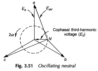
Three phase Transformer Bank of Single phase Transformers: The different Three phase Transformer Bank of Single phase Transformers are namely, Delta/delta connection: The supply voltage provides only sinusoidal magnetizing current so that core flux is flat-topped; but the third-harmonic emfs induced (cophasal) cause circulating currents in deltas restoring the flux to almost sinusoidal. The third-harmonic […]

Three phase Transformer Bank of Single phase Transformers Read More »

Choice of Transformer Connection Diagram

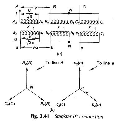
Choice of Transformer Connection Diagram: The different choice of Transformer Connection Diagram are namely, Star/star: This is economical for small HV transformers as it minimizes the turns/phase and winding insulation. A neutral connection is possible. However, the Y/Y connection is rarely used because of difficulties associated with the exciting current. Delta/delta: This Choice of Transformer

Choice of Transformer Connection Diagram Read More »

Three Phase Transformer Connections

Three Phase Transformers

Three Phase Transformer Connections: In generation, transformation, transmission and utilization of electric energy it can be shown that it is economical to use the three-phase system rather than the single-phase. For Three Phase Transformer Connections, three single-phase transformers are needed. Two arrangements are possible: a bank of three single-phase transformers or a single three-phase transformer

Three Phase Transformer Connections Read More »

Variable Frequency Transformer

Variable Frequency Transformer

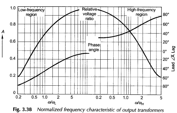
Variable Frequency Transformer | Application: So far we have considered transformers which operate at fixed frequency (50 Hz). Their purpose is to transform electric power from one voltage level to another; their performance measures being high efficiency and low voltage regulation. Small transformers (usually iron-cored) are used for coupling purposes in electronic circuits for communication,

Variable Frequency Transformer Read More »

Autotransformer

Auto Transformers

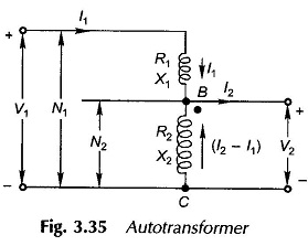
Autotransformer | Definition | Use of Auto transformer: So far two-winding transformers have been discussed wherein the windings are electrically isolated. When the primary and secondary windings are electrically connected so that a part of the winding is common to the two as shown in Fig. 3.35 (core is not shown here), the transformer is

Autotransformer Read More »

Switching Transients in Transformer

Switching Transient

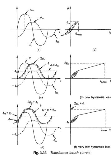
Switching Transients in Transformer | Transformer Inrush Current: Switching Transients in Transformer – In the earlier discussion earlier steady-state operation was assumed so that v1 and Φ are both sinusoidal, Φ lagging v1 by 90° as shown once again in Fig. 3.33(a). The Φ – i0 relationship is shown in Fig. 3.33(b). The normal exciting current

Switching Transients in Transformer Read More »

Excitation Phenomenon in Transformer

Excitation Phenomenon in Transformers

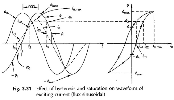
Excitation Phenomenon in Transformer: It was stated already that the no-load current in a transformer is nonsinusoidal. The basic cause for this Excitation Phenomenon in Transformer, which lies in Transformer Hysteresis and Saturation non­linearities of the core material, will now be investigated; this can only be accomplished graphically. Assume that the voltage v1 applied to

Excitation Phenomenon in Transformer Read More »

Transformer Efficiency Formula

Efficiency and Voltage Regulation

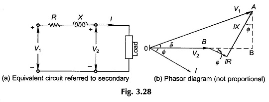
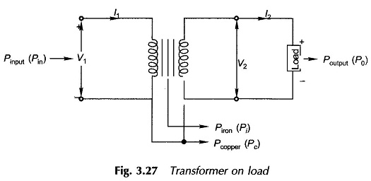
Transformer Efficiency Formula: Power and distribution transformers are designed to operate under conditions of constant rms voltage and frequency and so the efficiency and voltage regulation are of prime importance. Transformer Efficiency Formula is the rated capacity of a transformer is defined as the product of rated voltage and full load current on the output

Transformer Efficiency Formula Read More »

Per Unit System

Per Unit System: While carrying out the analysis of electrical machines (or electrical machine systems), it is usual to express voltage, current, VA and impedance in Per Unit System (or percentage) of the base or reference values of these quantities. The per unit (pu) value of any quantity is defined as the ratio of: While

Per Unit System Read More »

Scroll to Top