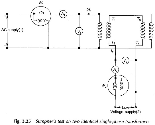
Sumpner Test of Transformer
Sumpner Test of Transformer: While OC and SC tests on a transformer yield its equivalent circuit parameters, these cannot be used for the 'heat run' test wherein the purpose is to determine the steady temperature…
Comments Off on Sumpner Test of Transformer
December 16, 2015