Basic Relays:
Most of the Basic Relays used in the power system operate by virtue of the current and/or voltage supplied by current and voltage transformers connected in various combinations to the system element that is to be protected. Through the individual or relative changes in these two quantities, faults signal their presence, type and location to the protective relays. Having detected the fault, the relay operates the trip circuit which results in the opening of the circuit breaker and hence in the disconnection of the faulty circuit.
Most of the Basic Relays in service on electric power system today are of elec o-mechanical type. They work on the following two main operating principles :
-
Electromagnetic attraction
-
Electromagnetic induction
1. Electromagnetic Attraction Relays:
Electromagnetic attraction relays operate by virtue of an armature being attracted to the poles of an electromagnet or a plunger being drawn into a solenoid. Such Basic Relays may be actuated by d.c. or a.c. quantities. The important types of electromagnetic attraction relays are :
(i) Attracted armature type relay: Fig. 21.3 shows the schematic arrangement of an attracted armature type relay. It consists of a laminated electromagnet M carrying a coil C and a pivoted laminated armature. The armature is balanced by a counterweight and carries a pair of spring contact fingers at its free end. Under normal operating conditions, the current through the relay coil C is such that counterweight holds the armature in the position shown. However, when a short cir suit occurs, the current through the relay coil increases sufficiently and the relay armature is attracted upwards. The contacts on the Basic Relays armature bridge a pair of stationary contacts attached to the relay frame. This completes the trip circuit which results in the opening of the circuit breaker and, therefore, in the disconnection of the faulty circuit.
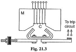
The minimum current at which the relay armature is attracted to close the trip circuit is called pickup current. It is a usual practice to provide a number of tappings on the relay coil so that the number of turns in use and hence the setting value at which the relay operates can be varied.
(ii) Solenoid type relay: Fig. 21.4 shows the schematic arrangement of a solenoid type Basic Relays. It consists of a solenoid and movable iron plunger arranged as shown. Under normal operating conditions, the current through the relay coil C is such that it holds the plunger by gravity or spring in the position shown. However, on the occurrence of a fault, the current through the relay coil becomes more than the pickup value, causing the plunger to be attracted to the solenoid. The upward movement of the plunger closes the trip circuit, thus opening the circuit breaker and disconnecting the faulty circuit.
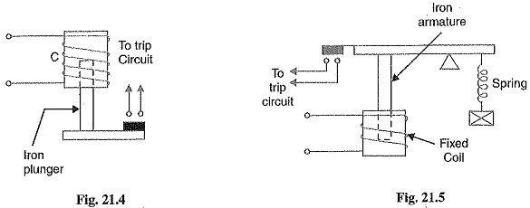
(iii) Balanced beam type relay: Fig. 21.5 shows the schematic arrangement of a balanced beam type relay. It consists of an iron armature fastened to a balance beam. Under normal operating conditions, the current through the relay coil is such that the beam is held in the horizontal position by the spring. However, when a fault occurs, the current through the relay coil becomes greater than the pickup value and the beam is attracted to close the trip circuit. This causes the opening of the circuit breaker to isolate the faulty circuit.
2. Electromagnetic Induction Relays:
Electromagnetic induction relays operate on the principle of induction motor and are widely used for protective relaying purposes involving a.c. quantities. They are not used with d.c. quantities owing to the principle of operation. An induction relay essentially consists of a pivoted aluminium disc placed in two alternating magnetic fields of the same frequency but displaced in time and space. The torque is produced in the disc by the interaction of one of the magnetic fields with the currents induced in the disc by the other.
To understand the production of torque in an induction relay, refer to the elementary arrangement shown in Fig. 21.6 (i). The two a.c. fluxes Φ2 and Φ1 differing in phase by an angle α induce e.m.f.s’ in the disc and cause the circulation of eddy currents i2 and i1 respectively. These currents lag behind their respective fluxes by 90°.
Referring to Fig. 21.6 (ii) where the two a.c. fluxes and induced currents are shown separately for clarity, let
where Φ1 and Φ2 are the instantaneous values of fluxes and Φ2 leads Φ1 by an angle α.
Assuming that the paths in which the rotor currents flow have negligible self-inductance, the rotor currents will be in phase with their voltages.
Fig 21.6 (ii) shows that the two forces are in opposition.
Net force F at the instant considered is
where Φ1 and Φ2 are the r.m.s. values of the fluxes.
The following points may be noted from exp. (i):
- The greater the phase angle a between the fluxes, the greater is the net force applied to the disc. Obviously, the maximum force will be produced when the two fluxes are 90° out of
- The net force is the same at every instant. This fact does not depend upon the assumptions made in arriving at exp. (i).
- The direction of net force and hence the direction of motion of the disc depends upon which flux is leading.
The following three types of structures are commonly used for obtaining the phase difference in the fluxes and hence the operating torque in induction relays:
- shaded-pole structure
- watt hour-meter or double winding structure
- induction cup structure
1. Shaded-pole structure: The general arrangement of shaded-pole structure is shown in Fig. 21.7. It consists of a pivoted aluminium disc free to rotate in the air-gap of an electromagnet. One-half of each pole of the magnet is surrounded by a copper band known as shading ring. The alternating flux Φs in the shaded protion of the poles will, owing to the reaction of the current induced in the ring, lag behind the flux Φu in the unshaded portion by an angle α. These two a.c. fluxes differing in phase will produce the necessary torque to rotate the disc. As proved earlier, the driving torque T is given by
Assuming the fluxes Φs and Φu to be proportional to the current I in the relay coil,
This shows that driving torque is proportional to the square of current in the relay coil.
2. Watt-hour meter structure: This structure gets its name from the fact that it is used in watt-hour meters. The general arrangement of this type of relay is shown in Fig. 21.8. It consists of a pivoted aluminium disc arranged to rotate freely between the poles of two electromagnets. The upper electromagnet carries two windings ; the primary and the secondary. The primary winding carries the relay current I1 while the secondary winding is connected to the winding of the lower magnet. The primary current induces e.m.f. in the secondary and so circulates a current I2 in it. The flux Φ2 induced in the lower magnet by the current in the secondary winding of the upper magnet will lag behind Φ1 by an angle α. The two fluxes Φ1 and Φ2 differing in phase by α will produce a driving torque on the disc proportional to Φ1Φ2 sin α.
An important feature of this type of relay is that its operation can be controlled by opening or closing the secondary winding circuit. If this circuit is opened, no flux can be set by the lower magnet however great the vaule of current in the pirmary winding may be and consequently no torque will be produced. Therefore, the Basic Relays can be made inoperative by opening its secondary winding circuit.
3. Induction cup structure: Fig. 21.9 shows the general arrangement of an induction cup structure. It most closely resembles an induction motor, except that the rotor iron is stationary, only the rotor conductor portion being free to rotate.
The moving element is a hollow cylindrical rotor which turns on its axis. The rotating field To trip circuit is produced by two St pairs of coils wound on four poles as shown. The rotating field induces currents in the cup to provide the necessary driving torque. If Φ1 and Φ2 represent the fluxes produced by the respective pairs of poles, then torque produced is proportional to Φ1Φ2 sin α where a is the phase difference between the two fluxes. A control spring and the back stop for closing of the contacts carried on an arm are attached to the spindle of the cup to prevent the continuous rotation.