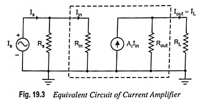
Equivalent Circuit of Current Amplifier
Equivalent Circuit of Current Amplifier: The input signal in a current amplifier is essentially a current, and thus the signal source is most conveniently represented by its Norton equivalent (Fig. 19.3). The output quantity of…
Comments Off on Equivalent Circuit of Current Amplifier
November 24, 2022