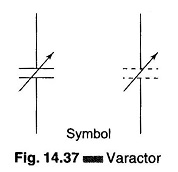
Varactor Diode Symbol:
A specially processed junction diode that assumes the properties of a variable capacitor (about 5 – 250 pf) when its dc reverse voltage is varied is called a Varactor Diode shown in Fig. 14.37.
This unique behavior can be used in special modulator circuits designed to turn a low voltage dc signal input into an ac output of proportional magnitude. A representative circuit is shown in Fig. 14.38.
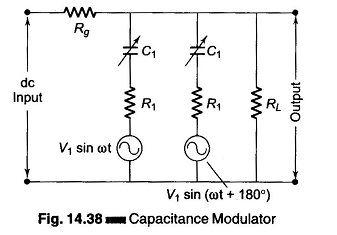
The modulator is essentially a ‘pumped’ parametric amplifier which can provide power gain. Assuming that the voltage variable capacitor (diodes) have the form C1 = Co + Kf(ν),
where
- Co = leakage capacitance,
- K = constant, and
- f(ν) = variable voltage function
The magnitude of the output voltage at RL can be shown to be proportional to the product of the magnitude of the carrier signal and the dc input signal supplied ahead of Rg. The system’s pump sources (carrier insertion) are provided by V1 and V2. These modulating units are usually composed in bridge configuration and the drift voltage of the modulator is limited by the precise balance of the two varicaps (varactor diode).