What is the Principle of Sweep Generator?:
Principle of Sweep Generator : The amplitude of a voltage may be directly measured on a calibrated viewing screen from the length of the straight line trace it produces. This is entirely satisfactory for dc voltage.
But the straight line tells little, or practically nothing, about the waveform of an ac voltage, pulsating voltage or transient. What is required is a graph of the voltage traced on the screen by the ac spot (a graph of amplitude versus time).
To obtain such a display the signal voltage is applied to the vertical plates (directly or through the vertical amplifier) and it moves the spot vertically to positions, corresponding to the instantaneous values of the signal. Simultaneously, the spot is moved horizontally by a sweep voltage applied to the horizontal plates. The combined action of these two voltages causes the spot to produce a trace on the screen. The horizontal sweep voltage produces the time base by moving the spot horizontally with time, while the signal moves the spot vertically in proportional to the voltage at a particular instant of time.
There are two important Principle of Sweep Generator requirements.
- The sweep must be linear (the sweep voltage must rise linearly to the maximum value required for full screen horizontal deflection of the spot).
- The spot must move in one direction only, i.e. from left to right only, else the signal will be traced backwards during the return sweep. This means that the sweep voltage must drop suddenly after reaching its maximum These requirements call for a sweep voltage having a linear sawtooth waveform, as shown in Fig. 7.3.
Now at time t0, the sweep voltage is – E2, and the negative horizontal voltage moves the spot to point 1 on the screen. At this instant, the signal voltage is 0, so the spot rests at the left end of the zero line on the screen.
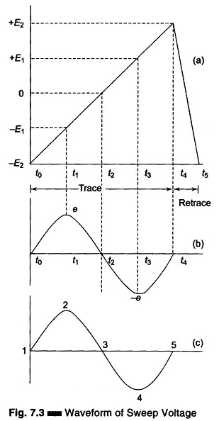
At time t1, the linearly increasing sawtooth reaches – E1, which, being more positive than – E2, moves the spot to the screen, point 2. At this instant, the signal voltage is e, the +ve peak value, so the point represents its maximum upward deflection of the spot. At time t2, the sawtooth voltage is 0, there is no horizontal deflection and the spot is at the centre, point 3. At this instant, the signal voltage is 0, so there is no vertical deflection either. At time t3, the sawtooth voltage is + E1, moving the spot to point 4.
At this instant, the signal is -e, the -ve peak value, so point 4 is the maximum downward deflection of the spot. At time t4, the sawtooth voltage is + E2, moving the spot to point 5. Now the signal voltage is 0, so the spot is not vertically deflected. Between t4 and t5, the sawtooth voltage falls quickly through 0 to its initial value of – E2, snapping the spot back to point 1, in time to sweep forward on the next cycle of signal voltage. When sweep and signal frequencies are equal, a single cycle appears on the screen, when the sweep is lower than the signal, several cycles appear (in the ratio of the two frequencies), and when sweep is higher than signal, less than one cycle appears. The display is stationary only when the two frequencies are either equal or integral multiples of each other. At other frequencies the display will drift horizontally. A sawtooth sweep voltage is generated by a multivibrator, relaxation oscillator or pulse generator. The upper frequency generated by internal devices in the oscilloscope is 50-100 kHz in audio instruments, 500-1000 kHz in TV service instruments and up to several MHz in high quality laboratory instruments. In some oscilloscopes the sweep is calibrated in Hz or kHz, and in others it is calibrated in time units (μs, ms, s).
The different types of Principle of Sweep Generator are as follows:
1. Recurrent Sweep:
When the sawtooths, being an ac voltage alternates rapidly, the display occurs repetitively, so that a lasting image is seen by the eye. This repeated operation is recurrent sweep.
2. Single Sweep:
The signal under study produces a trigger signal, which in turn produces a single sweep.
3. Driven Sweep:
The sawtooth oscillator is a free running generator when operated independently. There is a chance that the sweep cycle may start after the signal cycle, thereby missing a part of the signal. Driven sweep removes this possibility because it is fixed by the signal itself. The sweep and signal cycles start at the same time.
4. Triggered Sweep:
In a recurrent mode, the pattern is repeated again and again in this mode the voltage rises to a maximum and then suddenly falls to a minimum. The electron beam moves slowly from left to right, retraces rapidly to the left and the pattern is repeated. The horizontal sweep action takes place whether the input signal is applied to the oscilloscope or not, and a horizontal line is displayed on the scope screen.
A triggered sweep, on the other hand, does not start unless initiated by a trigger voltage, generally derived from an incoming signal. In the absence of the input signal, the sweep is held off and the CRT screen is blanked.
The continuous or recurrent sweep uses a free running multivibrator (m/v) which covers a wide frequency range and can be locked into synchronization by an input signal. Sync takes place when the sweep frequency and the input signal frequency are the same or when the former is a multiple of the latter.
A triggered scope does not use a continuous or recurrent sweep, but uses a monostable multivibrator which is in its off state until a trigger pulse arrives, hence there is no deflection on the screen.
When an input signal is applied, a trigger pulse is generated and applied to the multivibrator, which switches on and produces a sweep signal, and a trace appears on the screen. After a specific voltage, depending on the CRT beam arriving on the RHS, the multivibrator switches back to its off state, causing the beam to return rapidly to the LHS. (The basic difference between recurrent and triggered scopes is that the recurrent sweep locks at the frequency of the input signal, while the triggered scope displays a trace for a specific period of time. Hence, the triggered scope is ON during a specific time interval and will display a waveform or a segment of waveform (e.g. a one shot waveform) regardless of the signal frequency. Hence transients or single clamped oscillations can be observed on the screen.)
Most triggered scopes use a convenient feature of calibrating the sweep speed, in time per cm or division. Sweep frequency is the reciprocal of the time period.
5. Intensity Modulation:
In some applications an ac signal is applied to the control electrode of the CRT. This causes the intensity of the beam to vary in step with signal alternations. As a result, the trace is brightened during the +ve half cycles and diminished or darkened during -ve half cycles. This process, is called intensity modulation or Z-axis modulation (in contrast to X-axis for horizontal and Y-axis for vertical). It produces bright segments or dots on the trace in response to positive peak or dim segments or holes in response to negative peaks.