Short Circuit Protection Circuit:
Power supplies used in laboratories are subject to overloads and short circuits. Short Circuit Protection Circuit by means of current limiting circuits is necessary in such equipment to prevent the destruction of components when an overload occurs. Transistor Q7 and resistor R10 in Fig. 17-13(a) constitute a current limiting circuit.
When the load current (IL) flowing through resistor R10 is below the normal maximum level, the voltage drop VR10 is not large enough to forward bias the base-emitter junction of Q7. In this case, Q7 has no effect on the regulator performance.
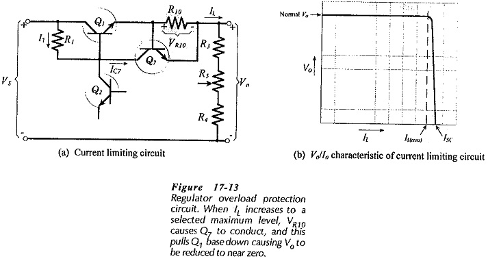
When the load current reaches the selected maximum (IL(max)), VR10 biases Q7 on. Current IC7 then produce a voltage drop across resistor R1 that drives the output voltage down to near zero.
The voltage/current characteristic of the regulator is shown in Fig. 17-13(b). It is seen that output voltage remains constant as the load current increases up to IL(max). Beyond IL(max), Vo drops to zero, and a short-circuit current (ISC) slightly greater than IL(max) flows at the output.
Under this circumstance, series pass transistor Q1 is carrying all of the short-circuit current and has virtually all of the supply voltage developed across its terminals.
So, the power dissipation in Q1 is,
![]()
Obviously, Q1 must be selected to survive this power dissipation.
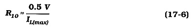
Design of the current limiting circuit in Fig. 17-13 is very simple. Assuming that Q7 is a silicon transistor, it should begin to conduct when VR10 ≈ 0.5 V. Therefore, R10 is calculated as,