Measurement of High Direct Current:
High magnitude direct currents are measured using a resistive shunt of low ohmic value. The voltage drop across the resistance is measured with a millivoltmeter. The value of the resistance varies usually between 10 μΩ and 10 mΩ. This depends on the heating effect and the loading permitted in the circuit. Measurement of High Direct Current resistors are usually oil immersed and are made as three or four terminal resistances. The voltage drop across the shunt is limited to a few millivolts (< I Volt) in power circuits.
Hall Generators for DC Measurements:
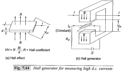
The principle of the “Hall effect” is made use of in Measurement of High Direct Current. If an electric current flows through a metal plate located in a magnetic field perpendicular to it, Lorenz forces will deflect the electrons in the metal magnetic field. The charge displacement generates an emf in the normal direction, called the “Hall voltage“. The Hall voltage is proportional to the current i, the magnetic flux density B, and the reciprocal of the plate thickness d; the proportionality constant R is called the “Hall coefficient“
![]()
For metals the Hall coefficient is very small, and hence semi-conductor materials are used for which the Hall coefficient is high.
In large current measurements, the current carrying conductor is surrounded by an iron cored magnetic circuit, so that the magnetic field intensity H—(1/δ) is produced in a small air gap in the core. The Hall elements is placed in the air gap (of thickness d), and a small constant d.c. current is passed through the element. The schematic arrangement is shown in Fig. 7.44. The voltage developed across the Hall element in the normal direction is proportional to the d.c. current I. It may be noted that the Hall coefficient R depends on the temperature and the high magnetic field strengths, and suitable compensation has to be provided when used for Measurement of High Direct Current.
Hall generators can be used for measurement of unidirectional a.c. and impulse currents also. With proper design of Hall element dimensions and addition of compensating circuits, the bandwidth of the Hall generator can be increased to about 50 MHz. As such, these generators can be used for the measurement of post arc currents and unidirectional impulse currents.
Measurement of High Power Frequency Alternating Currents:
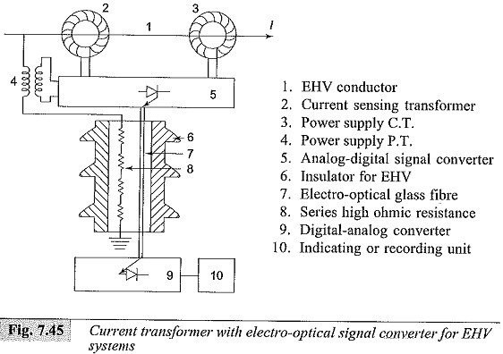
Measurement of power frequency currents are normally done using current transformers only, as use of current shunts involves unnecessary power loss. Also the current transformers provide electrical isolation from high voltage circuits in power systems. Current transformers used for extra high voltage (EHV) systems are quite different from the conventional designs as they have to be kept at very high voltages from the ground. A new scheme of current transformer measurements introducing electro-optical technique is described in Fig. 7.45. A voltage signal proportional to the measuring current is generated and is transmitted to the ground through an electro optical device. Light pulses proportional to the voltage signal are transmitted by a glass-optical fibre bundle to a photodetector and converted back into an analog voltage signal. Accuracies better than ± 0.5% have been obtained at rated current as well as for high short circuit currents The required power for the signal converter and optical device are obtained from suitable current and voltage transformers as shown in Fig. 7.45.
Measurement of High Frequency and Impulse Currents:
In power system applications as well as in other scientific and technical fields, it is often necessary to determine the amplitude and waveforms of rapidly varying high currents. Measurement of High Direct Current occur in lightning discharges, electrical arcs and post arc phenomenon studies with circuit breakers, and with electric discharge studies in plasma physics. The current amplitudes may range from a few amperes to few hundred kiloamperes. The rate of rise for such currents can be as high as 106 to 1012 A/s, and rise times can vary from few microseconds to measuring the signal over a wide frequency band. The methods that are frequently employed are
(i) resistive shunts,
(ii) magnetic potentiometers or probes, and
(iii) the Faraday and Hall effect devices.
The accuracy of measurement varies from 1 to 10%. In applications where only peak value measurement is required, peak reading voltmeters.