Principle of Induction Motor | Torque Slip Characteristic:
Principle of Induction Motor has not been introduced so far. Consider a cylindrical rotor machine with both the stator and rotor wound for three phases and identical number of poles as shown in Fig. 5.40. Assume initially the rotor winding to be open-circuited and let the stator be connected to an infinite bus ( V, f). The stator currents set up a rotating magnetic field in the air-gap which runs at synchronous speed inducing emf in the stator winding which balances the terminal voltage under the assumption that the stator resistance and leakage reactance are negligible. Also the rotating field induces emf in the rotor winding but no rotor current flows because the rotor is open-circuited. The frequency of rotor emf’s is of course f. Since the rotor mmf F2 = 0, no torque is developed and the rotor continues to be stationary. The Principle of Induction Motor acts merely as a transformer where the stator (primary) and rotor (secondary) have emf’s of the same frequency induced in them by the rotating magnetic flux rather than by a stationary time-varying flux as in an ordinary transformer.
 Let the rotor be now held stationary (blocked from rotation) and the rotor winding be short-circuited. The rotor now carries 3-phase currents creating the mmf F2 rotating in the same direction and with the same speed as the stator field. F2 causes reaction currents to flow into the stator from the busbar (just as in an ordinary transformer) such that the flux/pole Φr of the resultant flux density wave (rotating in the air-gap at synchronous speed) induces a stator emf to just balance the terminal voltage. Obviously Φr must be the same as when the rotor was open-circuited. In fact, Φr will remain constant independent of the operating conditions created by load on the motor. The interaction of Φr and F2, which are stationary with respect to each other, creates the torque tending to move the rotor in the direction of Fr or the stator field F1. The induction motor is therefore a self-starting device as different from the synchronous motor.
Let the short-circuited rotor be now permitted to rotate. It runs in the direction of stator field and acquires a steady speed of n. Obviously n < ns because if n = ns the relative speed between the stator field and rotor winding will be zero and therefore the induced emf’s and rotor currents will be zero and hence no torque is developed. The rotor thus cannot reach the synchronous speed ns and hence cannot exceed ns. With the rotor running at n, the relative speed of the stator field with respect to rotor conductors is (ns — n) in the direction of ns. The frequency of induced emf’s (and currents) in the rotor is therefore
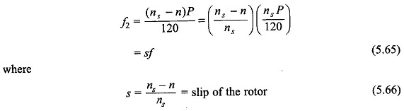
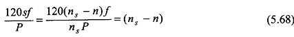
The slips s the per unit speed (with respect to synchronous speed) at which the rotor slips behind the stator field. The rotor frequency f2 = sf is called the slip frequency. From Eq. (5.66), the rotor speed is
![]()
The slip frequency currents in the rotor winding cause a rotor field rotating with respect to rotor in the same direction as the stator field at a speed of
Since the rotor is running at a speed n and the rotor field at (ns — n) with respect to the rotor in the same direction, the net speed of the rotor field as seen from the stator (ground reference) is
![]()
i.e., the same as the stator field. Thus the reaction field F2 of the rotor is always stationary with respect to the stator field F1 or the resultant field Fr (with flux Φr per pole). Since the rotor mmf F2 is proportional to the rotor current I2 and the resultant flux/pole Φr is fixed by terminal voltage independent of operating conditions, the induction motor torque is given by (see Eq. (5.58))
![]()
It is observed here that the torque is produced by the induction motor at any mechanical speed other than synchronous; such a torque is called the asynchronous torque.
The angle δ by which F2 lags behind Fr, the resultant mmf needs to be known. Before proceeding to determine δ, it must be observed that shorting the rotor winding is equivalent to shorting all the winding conductors individually. As a result the rotor does not necessarily have to be properly wound; it may be constructed of conducting bars placed in the rotor slots and shorted by conducting end-rings on each side of the rotor. Such a rotor is called the squirrel-cage rotor; the conducting cage is separately illustrated in Fig. 5.41. The squirrel-cage rotor has a cheap and rugged construction and is adopted in a vast majority of induction motor applications. The Principle of Induction Motor with a properly wound rotor is called the wound-rotor induction motor and is provided with three slip-rings which provide the facility of adding external resistance in the rotor winding before shorting these. Such motors are used in on-load starting situations.

Normally the full-load slip of a squirrel-cage induction motor is small 3-10%. Consequently the rotor impedance is mainly resistive, the rotor leakage reactance being proportional to f2 = sf is negligible. Furthermore, the rotor induced emf is proportional to the rotor-slip as Φr is fixed and rotates at speed ns – n = sns with respect to rotor.
This results in the rotor current being very nearly in phase with the rotor emf and proportional to the rotor slip. This conclusion would obviously apply to individual rotor conductors as well. Figure 5.42 shows the resultant flux density wave Br gliding past the rotor conductors at speed (ns – n) = sns in a developed diagram.
The induced currents in the shorted rotor conductors are sinusoidally distributed—the distribution moves at speed (ns – n) with respect to the rotor in synchronism with the Br-wave. Further, because the rotor conductors are assumed resistive, i.e. currents in them are in phase with their respective emf s, the rotor current distribution is in space phase with Br-wave. The sinusoidal rotor current distribution produces a sinusoidal rotor mmf wave F2 which lags 90° behind rotor current distribution or 90° behind Br-wave. It is, therefore, concluded that for small values of slip, the angle δ in the induction motor is 90°. Hence,
![]()
Since rotor emf is linearly proportional to slip, so is the rotor current for mainly a resistive rotor at small values of slip. Hence, the torque developed in the induction motor is a linearly increasing function of slip for small value of slip, being zero for s = 0, i.e. at synchronous speed.

As slip increases further, the leakage reactance of the rotor can no longer be neglected. Its value at slip s is sx2, where x2 is the rotor leakage reactance per phase at frequency f, i.e. when the rotor is at a stand-still. The rotor current now lags the rotor induced emf by
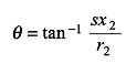
where r2 is the rotor resistance per phase.
Since the currents in the rotor conductors lag the induced emf’s by angle θ, the rotor conductor current distribution and therefore the rotor mmf F2 shifts to the left in Fig. 5.40 by an angle θ, so that
![]()
It means sin δ < 1. Further, since the rotor impedance is increasing with s, rotor current is less than proportional to slip. These two factors cause the motor torque to pass through a maximum value and then begin to decrease gradually as s is continuously increased.
The nature of the complete torque-slip characteristic of the induction motor is exhibited in Fig. 5.43. The maximum torque is known as the break-down torque. The motor would come to rest if loaded beyond a short time with torque load larger than the breakdown value.

As already mentioned, the slip of an induction motor is 3-10% at full-load. Therefore, it is substantially a constant speed drive unlike the synchronous motor which runs at constant speed independent of load.
Generating action results if an Principle of Induction Motor is run at negative slip or at speed n > ns, i.e. at a speed above synchronous.