DC Meter:
The most commonly used dc meter is based on the fundamental principle of the motor. The motor action is produced by the flow of a small amount of current through a moving coil which is positioned in a permanent magnetic field. This basic moving system, often called the D’Arsonval movement, is also referred to as the basic meter.
Different instrument forms may be obtained by starting with the basic meter movement and adding various elements of DC Meter as follows.
1. The basic meter movement becomes a dc instrument, measuring
- dc current, by adding a shunt resistance, forming a microammeter, a milliammeter or an ammeter.
- dc voltage, by adding a multiplier resistance, forming a milli voltmeter, voltmeter or kilovoltmeter.
- resistance, by adding a battery and resistive network, forming an ohmmeter.
2. The basic meter movement becomes an ac instrument, measuring
- ac voltage or current, by adding a rectifier, forming a rectifier type meter for power and audio frequencies.
- RF voltage or current, by adding a thermocouple-type meter for RF.
- Expanded scale for power line voltage, by adding a thermistor in a resistive bridge network, forming an expanded scale (100 — 140 V) ac meter for power line monitoring.
Basic Meter as a DC Voltmeter:
To use the basic meter as a dc voltmeter, it is necessary to know the amount of current required to deflect the basic meter to full scale. This current is known as full scale deflection current (Ifsd). For example, suppose a 50 μA current is required for full scale deflection.
This full scale value will produce a voltmeter with a sensitivity of 20,000 Ω per V.
The sensitivity is based on the fact that the full scale current of 50 μA results whenever 20,000 Ω of resistance is present in the meter circuit for each voltage applied.
Sensitivity = 1/Ifsd = 1/50μA = 20kΩ/V
Hence, a 0 – 1 mA would have a sensitivity of 1 V/1 mA = 1 kΩ/V or 1000 Ω.
DC Voltmeter:
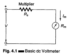
A basic D’ Arsonval movement can be converted into a dc voltmeter by adding a series resistor known as multiplier, as shown in Fig. 4.1. The function of the multiplier is to limit the current through the movement so that the current does not exceed the full scale deflection value. A dc voltmeter measures the potential difference between two points in a dc circuit or a circuit component.
To measure the potential difference between two points in a dc circuit or a circuit component, a dc voltmeter is always connected across them with the proper polarity.
The value of the multiplier required is calculated as follows. Referring to Fig. 4.1,
- Im = full scale deflection current of the movement (Ifsd)
- Rm = internal resistance of movement
- Rs = multiplier resistance
- V = full range voltage of the instrument
From the circuit of Fig. 4.1
Therefore

The multiplier limits the current through the movement, so as to not exceed the value of the full scale deflection Ifsd. The above equation is also used to further extend the range in DC voltmeter.
Multirange Voltmeter:
As in the case of an ammeter, to obtain a multirange ammeter, a number of shunts are connected across the movement with a multi-position switch. Similarly, a dc voltmeter can be converted into a multirange voltmeter by connecting a number of resistors (multipliers) along with a range switch to provide a greater number of workable ranges.
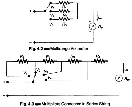
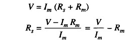
Figure 4.2 shows a multirange voltmeter using a three position switch and three multipliers R1, R2, and R3 for voltage values V1, V2, and V3. Figure 4.2 can be further modified to Fig. 4.3, which is a more practical arrangement of the multiplier resistors of a multirange voltmeter.
In this arrangement, the multipliers are connected in a series string, and the range selector selects the appropriate amount of resistance required in series with the movement.
This arrangement is advantageous compared to the previous one, because all multiplier resistances except the first have the standard resistance value and are also easily available in precision tolerances:
The first resistor or low range multiplier, R4, is the only special resistor which has to be specially manufactured to meet the circuit requirements.
Extending Voltmeter Ranges:
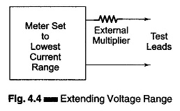
The range of a voltmeter can be extended to measure high voltages, by using a high voltage probe or by using an external multiplier resistor, as shown in Fig. 4.4. In most meters the basic movement is used on the lowest current range. Values for multipliers can be determined using the procedure of Section 4.4.
The basic meter movement can be used to measure very low voltages. However, great care must be used not to exceed the voltage drop required for full scale deflection of the basic movement.
Sensitivity:
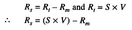
The sensitivity or Ohms per Volt rating of a voltmeter is the ratio of the total circuit resistance Rt to the voltage range. Sensitivity is essentially the reciprocal of the full scale deflection current of the basic movement. Therefore, S = 1/Ifsd Ω/V
The sensitivity ‘S’ of the voltmeter has the advantage that it can be used to calculate the value of multiplier resistors in a dc voltmeter. As,
- Rt = total circuit resistance [Rt = Rs + Rm]
- S = sensitivity of voltmeter in ohms per volt
- V = voltage range as set by range switch
- Rm = internal resistance of the movement
Since
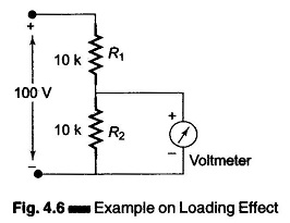
Loading:
When selecting a meter for a certain voltage measurement, it is important to consider the sensitivity of a dc voltmeter. A low sensitivity meter may give a correct reading when measuring voltages in a low resistance circuit, but it is certain to produce unreliable readings in a high resistance circuit. A Voltmeter when connected across two points in a highly resistive circuits, acts as a shunt for that portion of the circuit, reducing the total equivalent resistance of that portion as shown in Fig. 4.6. The meter then indicates a lower reading than what existed before the meter was connected. This is called the loading effect of an instrument and is caused mainly by low sensitivity instruments.