Commutation in DC Motor:
Commutation and commutator wear and tear of the dc motor must be given due consideration when the motor operates on solid state converters. Spark-less commutation must be aimed at. The reactance voltage and dynamically induced voltage in the coil undergoing commutation affect the rate of change of current in the coil. Interpoles are provided to establish a flux to compensate for the above voltages and to achieve sparkless commutation. The Commutation in DC Motor is sparky when the field is weak, the load current is high and the speed is large. The dc motor must be used on power converters with a caution because commutation problems occur. These problems are due to
1.ripple content of the armature current.
2.discontinuous conduction.
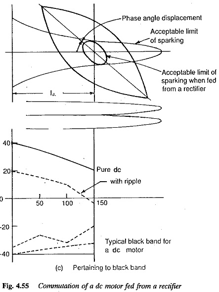
The Commutation in DC Motor fed from a normal dc supply and rectified power supply is shown in Fig. 4.55.
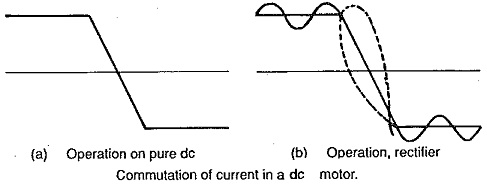
The Commutation in DC Motor is deteriorated by the ripple of the armature current in the following ways:
1.Peak/average value of current is more. The increased peak value has to be actually commutated and causes wear and tear at the brushes if the number of pulses occurring per brush is more than one in number.
2.The magnitude of armature current immediately after commutation is rather indefinite due to slope of the current. This also results in indefinite value of time when the Commutation in DC Motor bar leaves the brush.
3.The ripples produce eddy currents and associated fluxes in the interpoles. These additional fluxes react with the flux produced by average current. There is a phase shift in the interpoles flux. This modified flux is not in a position to compensate the reactance voltage.
4. The armature current ripple increases the reactance voltage of the coil undergoing commutation.
5.Discontinuous conduction affects the commutation. When there is discontinuous conduction the output voltage of the converter is greater than what would occur with continuous conduction at the same firing angle. This deteriorates commutation by increasing bar to bar voltage and peak/average current ratio.
The machine is more vulnerable to sparking if the peak/average current ratio is more. The Commutation in DC Motor capability of the motor is measured in terms of the width of the blackband. The narrower the band, greater the possibility of sparking at the brushes. This band is determined by a test in which the current in the interpole winding is bucked and boosted from its operating point until sparking occurs. The limits of this current represent blackband and can be represented as per unit of rated current. The wider this band, more satisfactory the commutation. The band width decreases when the armature has increased ripple and speed is high.
Satisfactory Commutation in DC Motor can be achieved in a dc motor by the following modifications:
1.The peak value of the armature current can be controlled by increasing the pulse number of the converter. Additional inductance in the armature circuit helps improve the commutation. The inductance may be designed such that it contributes at lower currents where the ripple is high. It gets saturated at high currents where the ripple is less. The machine itself can be designed so that its armature has inherently large inductance. This is done by making the field weak, armature large and air gap small.
2.The commutating capability of the motor can be improved by laminating the frame as well as the interpole body. These reduce the effective phase shift in the interpole flux due to eddy fluxes caused by the ripple content. With this type of motor a converter with less number of pulses can also be used.
3.Discontinuous conduction is also reduced to a minimum by the additional inductance. The choice of inductance is made to avoid discontinuous conduction rather than smooth the output ripple.
Speed-torque characteristic : A dc motor which is fed from a converter shows a very poor speed regulation compared to the operation on a normal dc supply. This is more pronounced at low speeds and low torques. The average current is representative of the torque developed. As has already been explained, with converter supplies average current is small for a given armature heating. Discontinuous conduction affects speed regulation. This can be improved by means of a FWD or a semi converter.
Line side performance : The converter operation affects the line performance also. As the converter firing angle is retarded to get low speeds the power factor becomes poor. This is because of the reactive power requirement of the converter and also the harmonic content of the line current. The line power factor can be improved by use of semi converters and converters with FWD. An inductance on the load side also improves the harmonic content on the line side. The drive is not capable of regeneration.
Additional Losses and Low Speed Operation
The distorted armature current of the d.c. motor fed from phase controlled converter causes additional losses in the armature conductors. These losses are due to the increased RMS value of the armature current and also the possible skin effect of the armature conductors. The skin effect causes an increase in the effective resistance of the armature. The additional losses may be present in the interpole winding and compensating winding. The interpoles may also have additional iron losses.
However, the increase in the losses is significant only in respect of temperature rise but not efficiency. The increase in temperature rise may lead to a de-rating of the motor. The increase in the firing angle of the converter increases the ripple factor of current waveform. So, as the value of a increases these additional losses may be more and resulting derating is also more. Further the motor speed decreases as a increases. At low speeds the natural ventilation is poor. If there is no provision for additional ventilation, this will also cause a further derating of the motor. Therefore a d.c. motor operating on phase controlled converters cannot be fully loaded, particularly at low speeds.
Phase Controlled Converter Fed dc Drives
A detailed discussion has been given how the converter operation affects the performance. There are several types of converters which can be, used for feeding dc motors. These were described in Chapter 3 in detail. To arrive at a suitable converter-motor system an evaluation of the performance of a dc motor operating on different types of converter may be required. A systematic description of these drives is given below. The parameters of importance are as follows:
(a) on the motor side:
1.average current of the motor representative of torque developed
2.rms value of the current which represents the motor heating and losses
3.peak value of current which represents commutating capability of the motor
4.nature of current whether continuous or discontinuous
5.torque-speed characteristic, associated speed regulation, etc
(b) on the line side:
1.fundamental displacement factor
2.harmonic factor
3.total power factor of the system.
Single phase drives
In these drives phase controlled converters operating from a single phasare used to drive the motor. These are used for low and medium power applications. These have inherently poor speed regulation with open loop control. This can be improved with closed loop operation.
These drives can be half wave or full wave drives.. A full wave drive can be supplied from a fully controlled or half controlled converter. The former is capable of two quadrant operation whereas only one quadrant operation is possible with the latter, as it contains diodes in several positions. A dual converter can be obtained by a connection of two two-quadrant converters. Table 1 summarises these drives.