Circular Waveguide:
It should be noted from the outset that in general terms the behavior of waves in circular waveguide is the same as in rectangular guides.
Analysis of behavior:
The laws governing the propagation of waves in waveguides are independent of the cross-sectional shape and dimensions of the guide. As a result, all the parameters and definitions evolved for rectangular waveguides apply to circular waveguides, with the minor modification that modes are labeled somewhat differently. All the equations also apply here except, obviously, the formula for cutoff wavelength. This must be different because of the different geometry, and it is given by
![]()
where
r = radius (internal) of waveguide
(kr) = solution of a Bessel function equation
To facilitate calculations for circular waveguides, values of (kr) are shown in Table 10-2 for the circular waveguide modes most likely to be encountered.
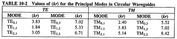
One of the differences in behavior between circular and rectangular waveguides is shown in Table 10-2. Since the mode with the largest cutoff wavelength is the one with the smallest value of (kr), the TE1,1 mode is dominant in circular waveguides. The cutoff wavelength for this mode is λ0 = 2πr/1.84 = 3.41r = 1.7d, where d is the diameter. Another difference lies in the different method of mode labeling, which must be used because of the circular cross section. The integer m now denotes the number of full wave intensity variations around the circumference, and n represents the number of half-wave intensity changes radially out from the center to the wall. It is seen that cylindrical coordinates are used here.
Other Waveguides:
There are situations in which properties other than those possessed by rectangular or circular waveguides are desirable. For such occasions, ridged or flexible waveguides may be used.
Ridged Waveguides:
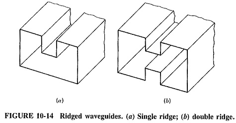
Rectangular waveguides are sometimes made with single or double ridges, as shown in Figure 10-14. The principal effect of such ridges is to lower the value of the cutoff wavelength. In turn, this allows a guide with smaller dimensions to be used for any given frequency. Another benefit of having a ridge in a waveguide is to increase the useful frequency range of the guide. It may be shown that the dominant mode is the only one to propagate in the ridged guide over a wider frequency range than in any other waveguide. The ridged waveguide has a markedly greater bandwidth than an equivalent rectangular guide. However, it should be noted that ridged waveguides generally have more attenuation per unit length than rectangular waveguides and are thus not used in great lengths for standard applications.
Flexible Waveguides:
It is sometimes required to have a waveguide section capable of movement. This may be bending, twisting, stretching or vibration, possibly continuously, and this must not cause undue deterioration in performance. Applications such as these call for flexible waveguides, of which there are several types. Among the more popular is a copper or aluminum tube having an elliptical cross section, small transverse corrugations and transitions to rectangular waveguides at the two ends. These transform the TE1,1 mode in the flexible waveguide into the TE1,0 mode at either end. This waveguide is of continuous construction, and joints and separate bends are not required. It may have a polyethylene or rubber outer cover and bends easily but cannot be readily twisted. Power-handling ability and SWR are fairly similar to those of rectangular waveguides of the same size, but attenuation in dB/m is about five times as much.